| START HERE |
|
| Register | FAQ | PM | Events | Groups | Blogs | Calendar | Mark Forums Read |
|
|
|
Unregistered
|
||||||


| Gas Powered Thoughts Advice for Gas Helicopter Success from Carey Shurley |
|
|
 |
|
|
LinkBack | Thread Tools | Display Modes |
 05-02-2014, 09:35 PM
|
#1 (permalink) |
|
Registered Users
Join Date: Apr 2004
|
Trex 600 Conversion for GT15-600 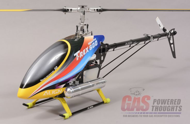 Overview Recently I presented the OS Max GT15-600 engine. I also noted that there were not very many models available that it could be installed in One of the available models is a conversion for a Trex 600 nitro model. Its distributed by OS Max. Lets go over what it consists of The conversion is packaged as shown 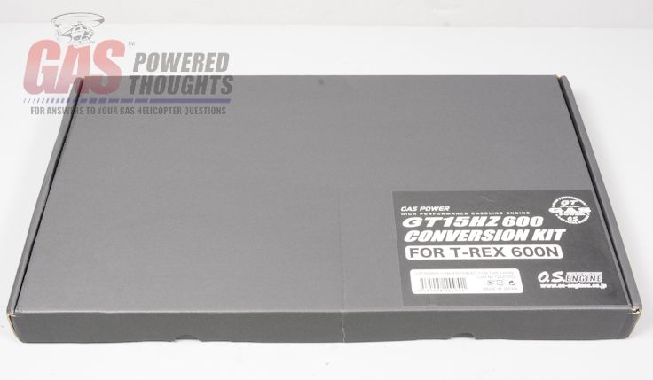 Conversion Kit Box Here's what you find in side.
The graphite parts are cut cleanly and the machining on the metal parts is well done 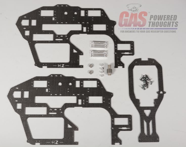 Conversion Contents Here you can see the two engine mounts as well as the new pinion gear 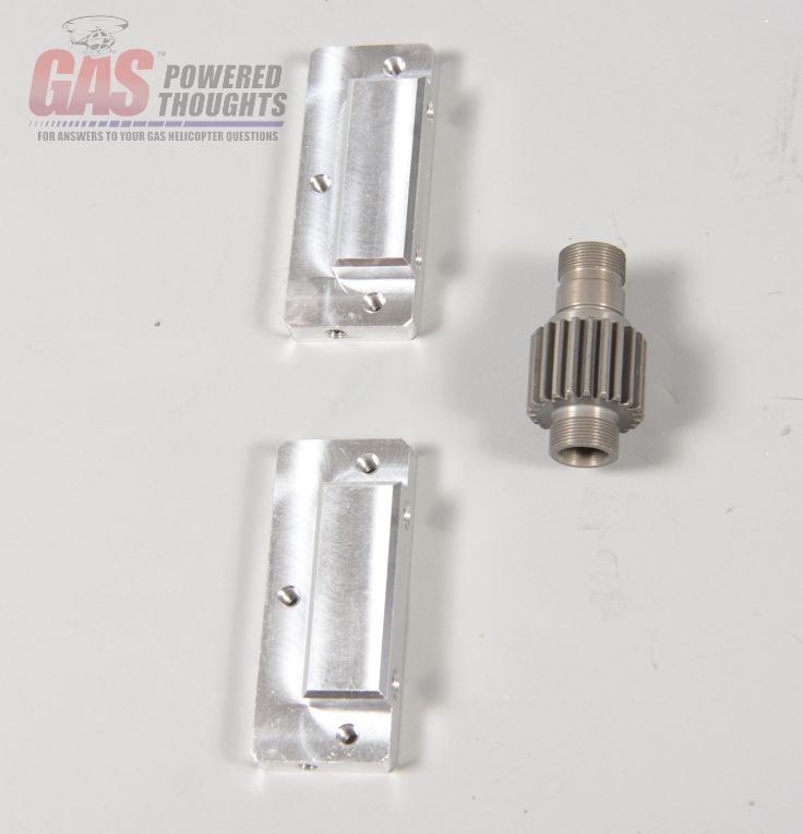 Engine Related parts The conversion comes with a pretty simple conversion guide, its four pages hardcopy. Here are the instructions 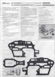 Click image to see Instruction Manual Donor Parts Needed Its a conversion, so you need a donor model to convert. In this case its a Trex 600 nitro model. In basic terms this conversion isn't that different from using the original glow motor, its just larger so you're going to need most of the original model you will not need the original side frames or bottom plate, the cooling fan or the fan shroud 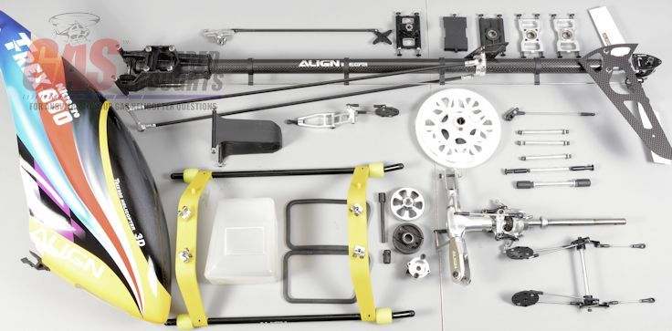 Trex 600 Donor Parts Also like most conversions you need some additional parts but much fewer than is normal for these things. You need a fan shroud from a Trex 700 DFC and an aftermarket high volume T600 fan. You'll also need gasoline proof tubing and the standard fuel clunk. I tried to use a felt clunk but the pump doesn't pull fuel consistently through it. Its important to note, the fan shroud HAS to be from the DFC kit because its more narrow. Part number is H7NB011XX 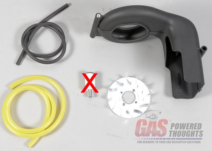 Additional Parts Although the fan shroud for the Trex 700 comes with a cooling fan, its recommended by OS to replace it with a high volume fan. Obviously this is a gasoline engine which runs much hotter than any glow engine so making the cooling system as effective as possible is important. Here you can see the std Trex fan on the left and the G-Force fan on the right. It will bolt directly onto the original Trex 600 fan hub you can also use the Align CNC fan part number HN6060 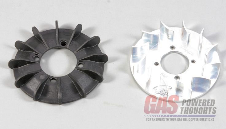 Trex 700 Fans compared you'll also need the OS Max GT15-600 engine. If you have the original GT15-HZ it will not work out of the box because the crank size is different and won't fit the Trex 600 fan hub. 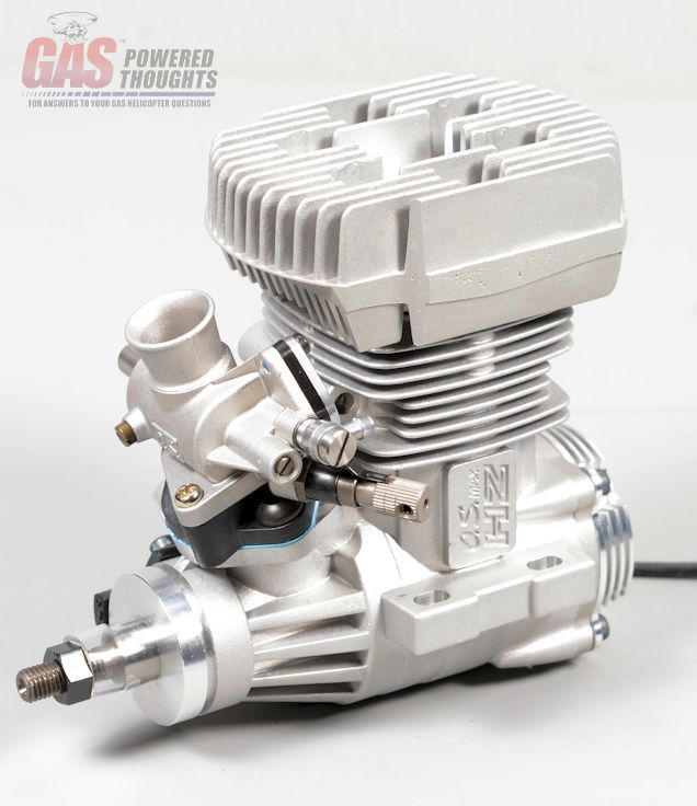 OS Max GT15-600 you'll also need a properly designed exhaust for the engine, OS Max produces the Powerboost pipe, this is the same pipe used on the GT15-HZ engine 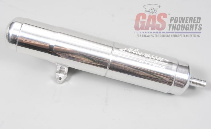 GT15 Powerboost pipe the engine includes both an ignition system 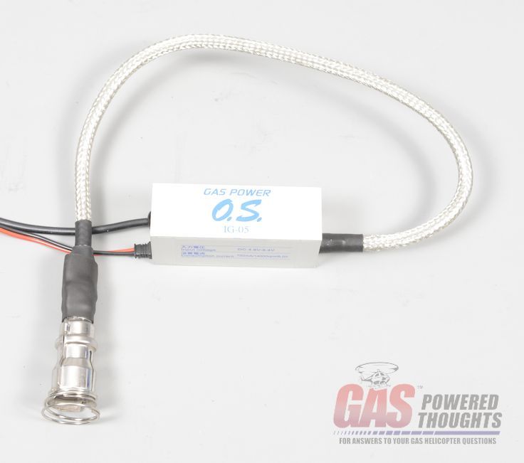 GT15 Ignition system as well as a special fuel pump. The GT15-HZ engine used a carburetor with a built in fuel pump. The GT15-600 uses a different carburetor that does not include a pump. So OS includes this fuel pump that is driven by case pressure  GT15-600 fuel pump Whats unique about these last two items is that the conversion frames have specific mount points included for both. Next Step Frame Conversion Last edited by carey shurley; 02-07-2019 at 05:51 AM.. |

|


|
| Sponsored Links | |||
|
Advertisement |
|
||
|
06-14-2014, 09:55 PM
|
#2 (permalink) |
|
Registered Users
Thread Starter

Join Date: Apr 2004
|
The bulk of the conversion will be done in this step. You'll see that its pretty simple and well thought out
Converting The Chassis If you follow my build threads you know that I rarely follow the assembly order in the manuals, I tend to pre-build assemblies which speeds the assembly process quite a bit. This will be no different. Pre-Assembly If you're converting an existing model then all of these components will already be built. If you're building from a kit then all of these components can be pre-assembled according to the original manual 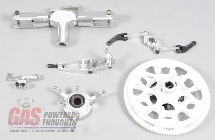 Components to complete Because this conversion uses gasoline, some of the parts in the fuel tank will have to be changed to gasoline resistant parts I always suggest using a felt clunk, this is a Stens clunk which will fit into the tank without enlarging the hole. The inlet line also either needs to be viton or neoprene. Everybody seems to have their own preference as to what length they like to run these so cut to your own preference 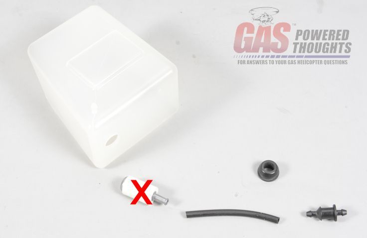 Fuel tank Parts Assemble the parts like this, slip the felt filter up onto the line, you'll see why 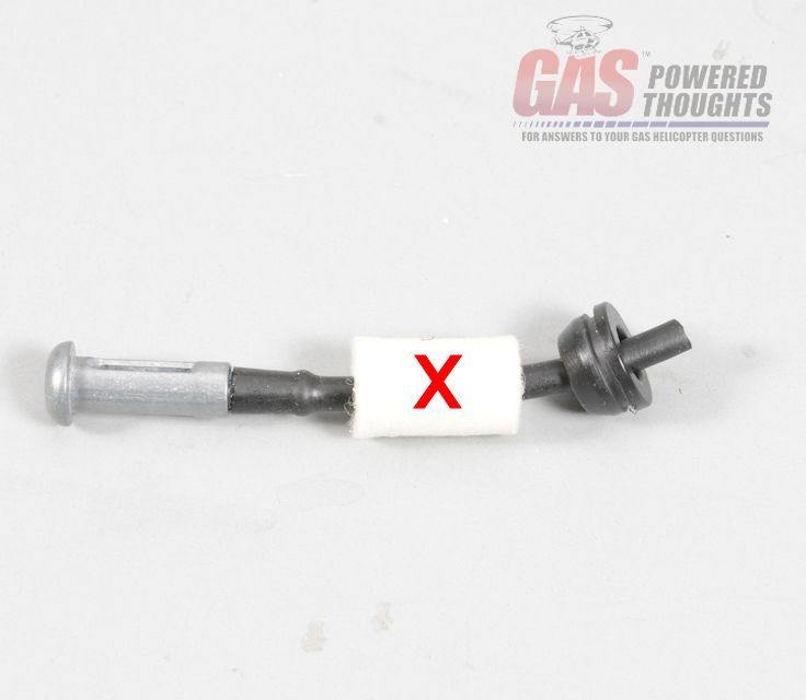 Assemble fuel inlet The assembled clunk will be very hard to get through the tank hole but if you slip the filter up on the line its very easy to push the parts through. Then seat the grommet in the tank  Install Fuel Inlet now gently pull the fuel line out until the filter reseats on the clunk. Don't pull so hard the tubing comes off of the clunk though 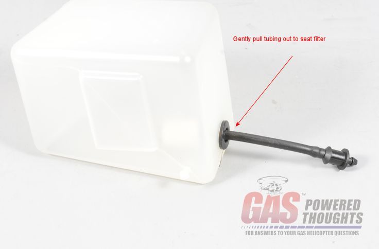 Seat Fuel Filter Now just seat the fuel outlet into the grommet and the tank is done. You might use some oil on the fuel tubing or fittings to make the assembly more smooth 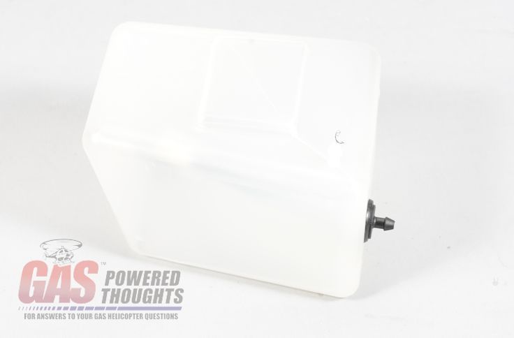 Fuel Tank Completed Also, the entire tail boom assembly can be assembled if you're building from a kit, otherwise you'll need the entire tail boom Frame Asssembly These are the parts you need to build the first frame half, which in this case will be the left frame 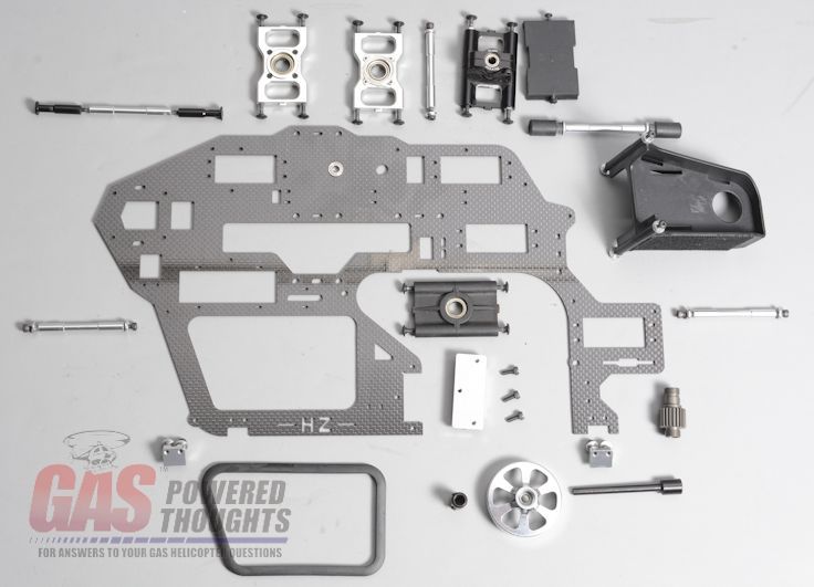 Parts to complete Chassis The conversion includes two flange bearings for the elevator bearings. The frame halves are identical but must be assembled in opposites. So Install the two bearings from the "outside" of each frame half. Use CA to hold the bearings in place 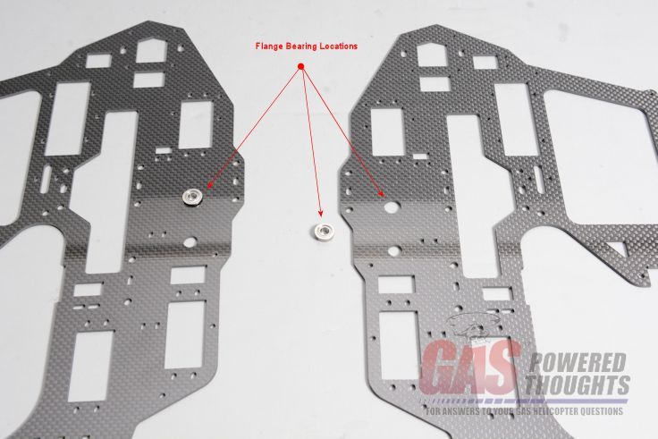 Install Elevator Bearings The conversion kit includes a 22T pinion gear. If you a converting a built kit, then disassemble the clutch. Locate this bearing and nut and install it on the new pinon 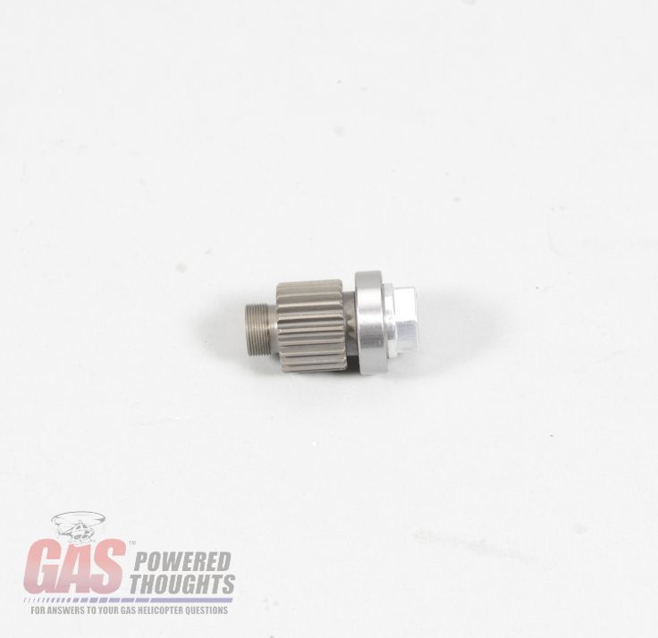 Prepare Pinion Then assemble/reassemble the clutch stack in the normal fashion 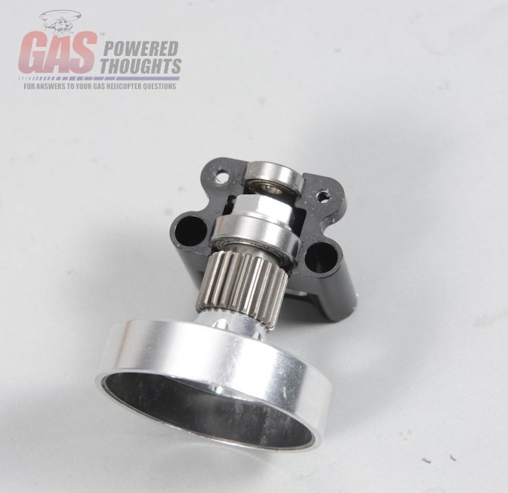 Assemble Clutch when done, the new clutch assembly will be ready to install in the conversion frames 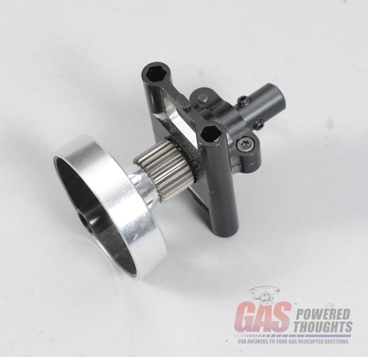 Completed Clutch Select what will be the left frame. The flange on the elevator bearing should be on the outside and the letters HZ at the bottom should appear backwards. Locate one of the engine mounts from the conversion and install on the left frame as shown 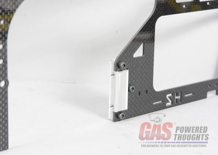 Install Left Engine Mount Now install all of the frame parts onto the left frame using the original fasteners. Use the mainshaft to align the bearing blocks. Fully tighten with thread lock where appropriate. This is how it looks when done from the inside 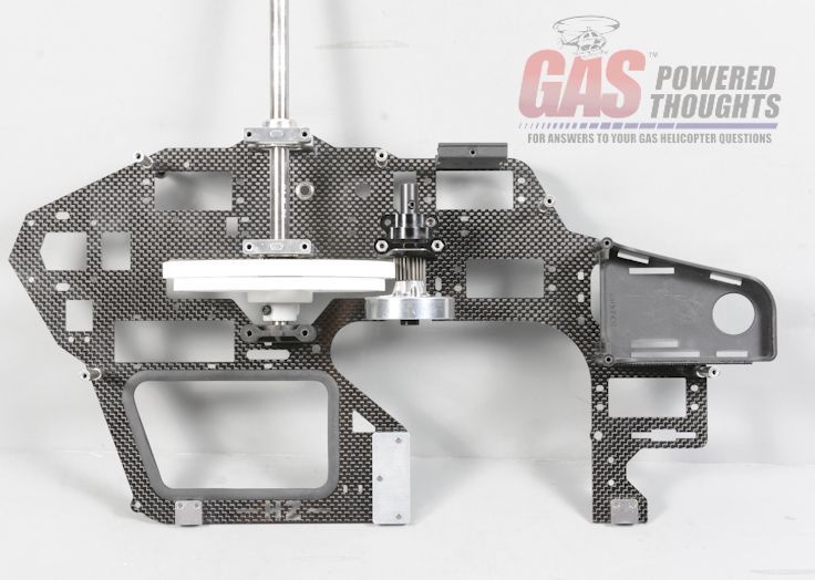 Completed Left Frame - Inside and this is what you should see when looking at the left frame from the outside 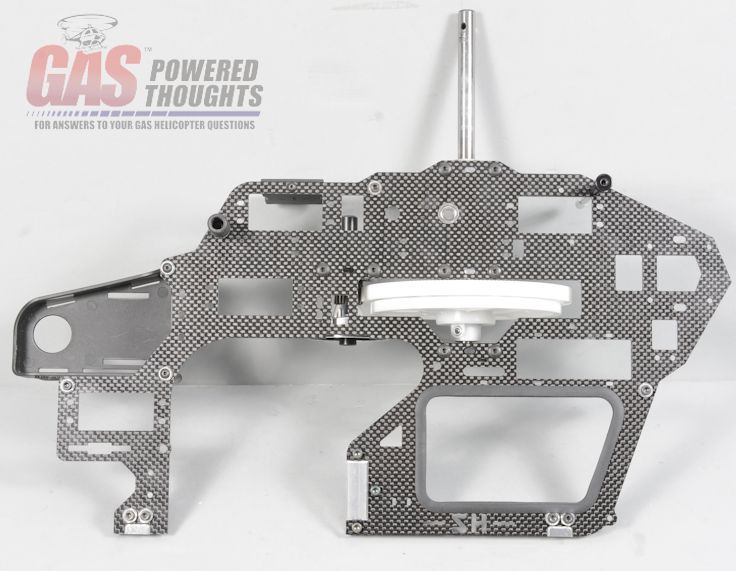 Completed Left Frame - Outside Now find the right frame and prepare it for installation. Install the remaining engine mount, the tank isolator and the landing gear mounts. Also install the fuel tank. Here's what you should see when viewing from the outside of the frame 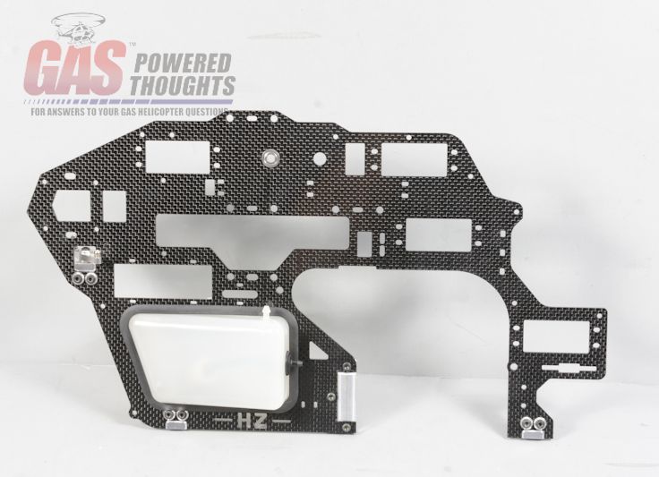 Prepared Right Frame - Outside and here's what you should see when looking at the inside of the frame 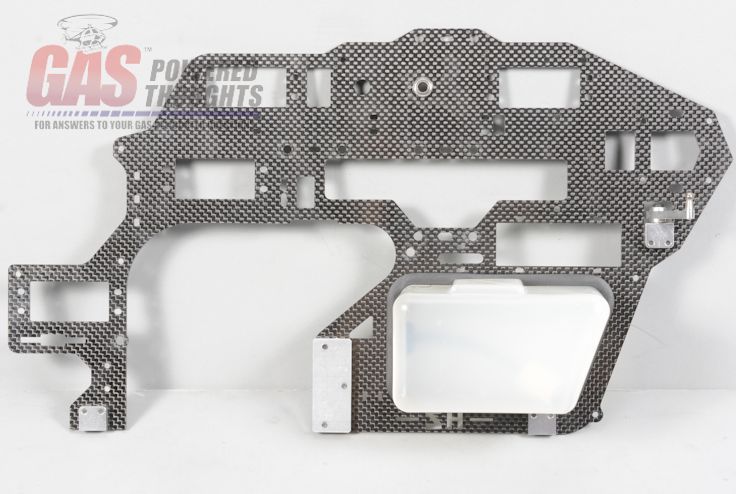 Prepared Right Frame - Inside Now assemble the frame halves using all the original fasteners. Use thread lock where appropriate. Heres how it looks from the right side 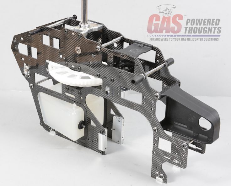 Assembled Frames - Right Side and the assembled frames from the left side 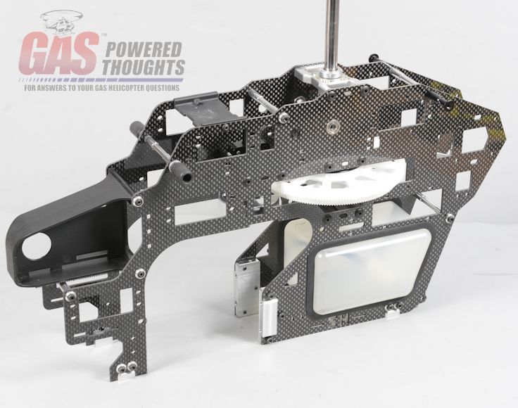 Assembled Frames - Left Side With the frames combined, the frame bottom can be installed. The conversion includes a special plate and you'll need the original landing gear 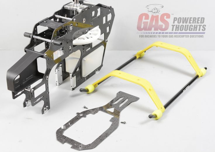 Frame Bottom Parts Install the bottom plate to the assembled frames using the M3 bolts included with the conversion. Note the position of the mount for the GT15 fuel pump. It will be installed in the next step 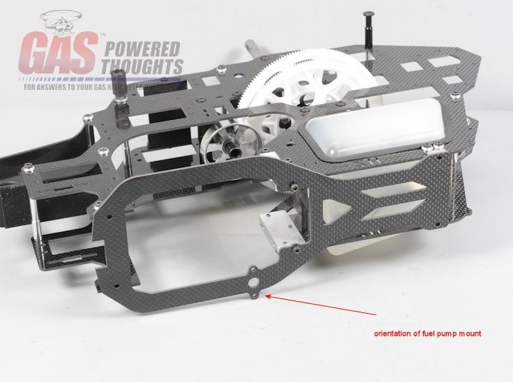 Bottom Plate Installed With the bottom plate in place, install the landing gear in its original position 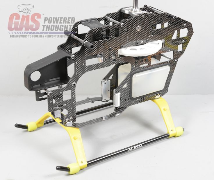 Landing Gear Installed Partially completed chassis 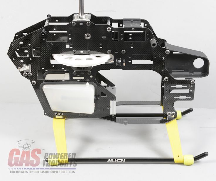 Basic Chassis converted Install the elevator/ail/pitch bellcranks. These will install through the bearings installed into the frames. You'll have to adjust the spacing using the washers originally provided with the donor kit 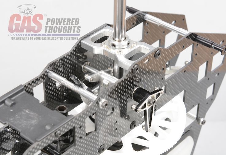 Install Swashplate Control components Now the rest of the rotor head parts can be installed/connected 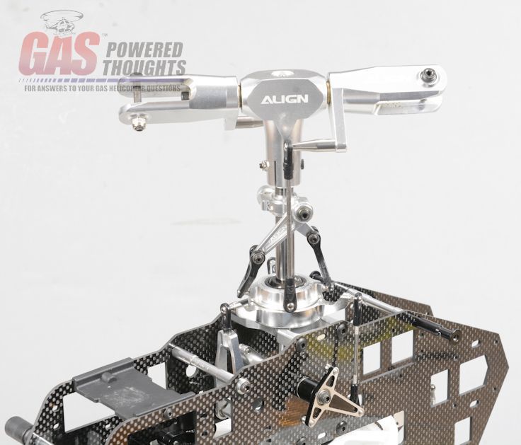 Install Rotor head components Finally the complete tail boom can be installed 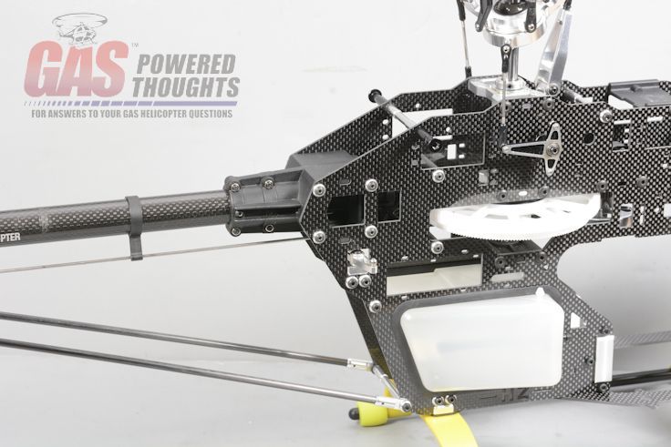 Install Complete tail boom At this point, the "conversion" is really done, the only thing left is to install the engine itself Next Step Install Engine Last edited by carey shurley; 02-07-2019 at 05:52 AM.. |
|
|
|
|
06-23-2014, 05:46 PM
|
#3 (permalink) |
|
Registered Users
Thread Starter
Join Date: Apr 2004
|
Install Engine
With the chassis completed now the engine can be installed. Really the engine, EI system and fuel pump will be installed. The std Trex 600 fan hub and clutch will be used however you must use a high volume fan. Align offers one as do other manufacturers 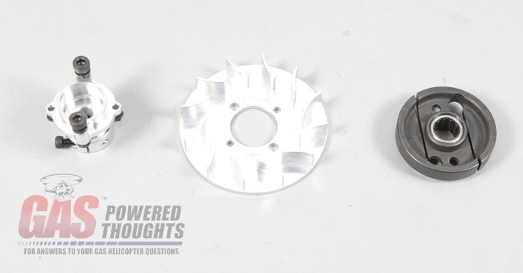 Hub/Fan/Shroud Here you can see the difference between the stock Trex fan and the Align metal fan. The fins are much larger 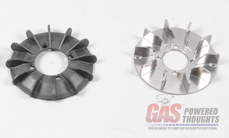 High volume fan vs std fan Assuming you want to run a governor or an RPM telemetry sensor, you'll need to install the magnets in the fan using an adhesive. Here you can see them installed. This is actually the top of the fan 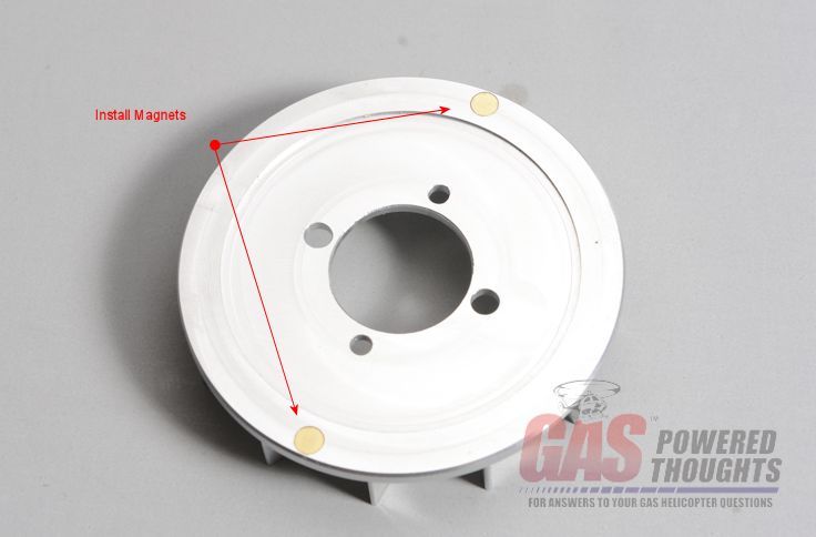 Install sensor magnets With the fan mounted on the hub you can see which side is "up" 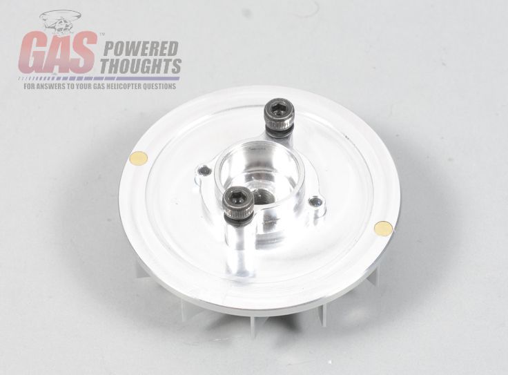 Assemble fan hub To mount the fan hub, the crank on the engine needs to be locked. Remove the backplate from the engine and use something small and non metallic (like a toothbrush) block the rod as shown 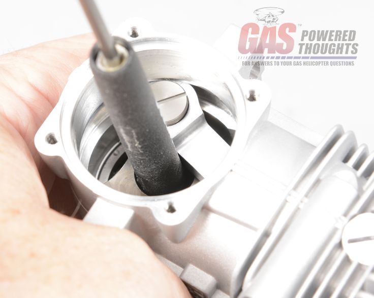 Lock crank Push the fan hub over the crankshaft end and tighten down the crank nut until the hub seats on the top of the timing ring on the engine. Once this is done you can re-install the engine backplate 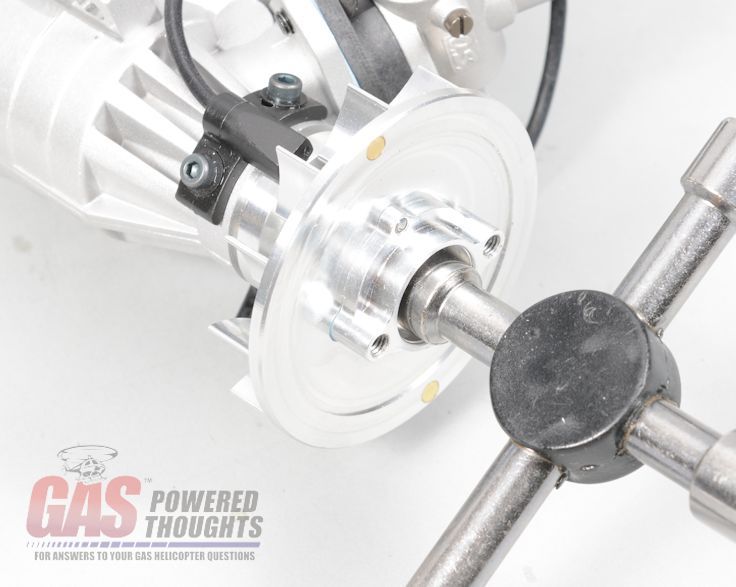 Tighten fan hub The Trex 600 clutch can be installed as well 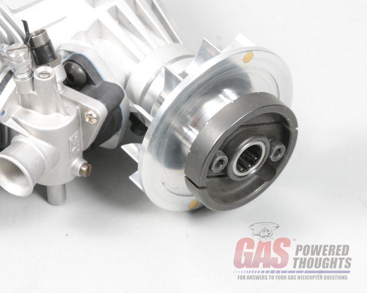 Install clutch The conversion specifies that the fan shroud from a 700 DFC must be used. The reason is the width of the mounts. The DFC frame is more narrow. A std 700N fan shroud won't fit between the conversion frames because its too wide 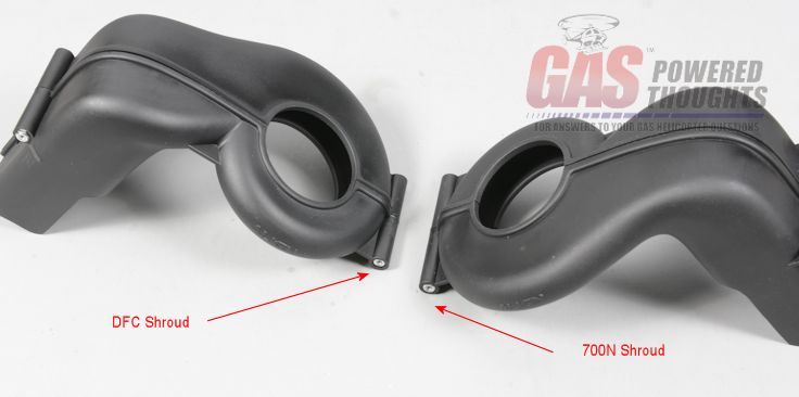 DFC vs 700N Shroud In order to install the shroud, some adjustments need to be made as the GT15-600 engine is slightly different than a std OS91. This regulator will interfere with the fan shroud and the shroud must be adjusted for it to fit 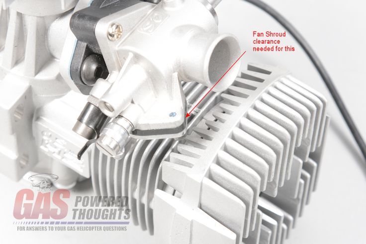 Shroud interference Trial fit the shroud until you can determine the exact position that needs to be relieved and remove this small section of the shroud Relieve fan shroud You also need to open up the "glow plug" hole so that the larger EI plug cap will fit through it 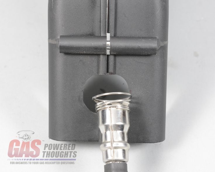 Open Shroud for plug cap I would HIGHLY recommend installing a telemetry temperature sensor. This engine runs much hotter than a std glow engine so its helpful to understand running temperature. I'd suggest putting a "loop" sensor here  Install temp sensor and route the sensor lead like this 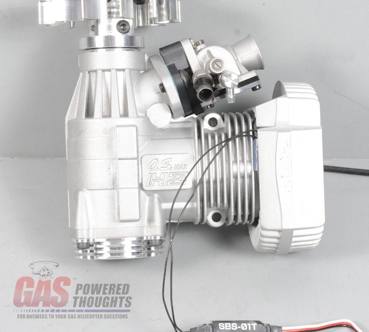 Temp sensor installed If you intend to run a governor or telemetry RPM sensor, you need to mount the sensor. On the Trex 600 it installs here. I tried every conceivable way to use the Stator Gator but I couldn't get any of them to work 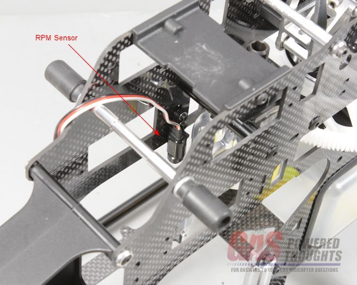 RPM sensor installed If you are using a std RPM sensor, you need to relieve the fan shroud so that the sensor can align with the fan magnets. Trial fit the shroud until you can determine the right position to cut the fan shroud as shown 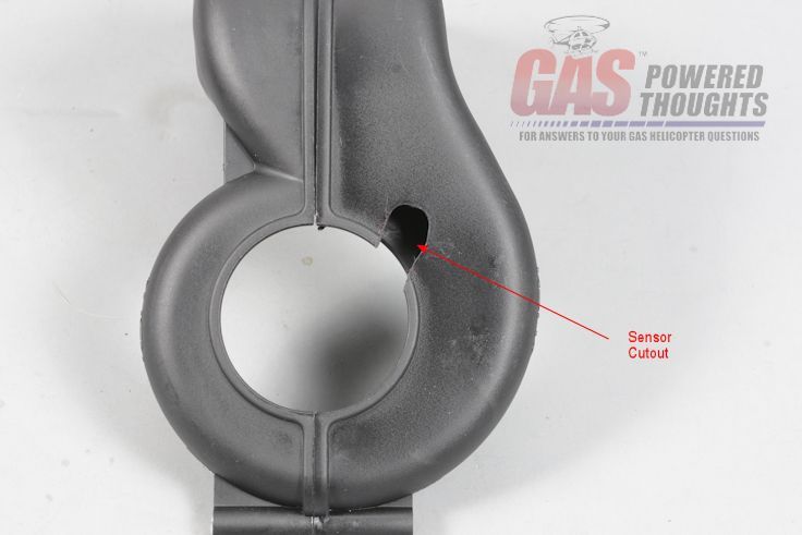 Relieve shroud for RPM sensor Now go ahead and put the fan shroud over the fan 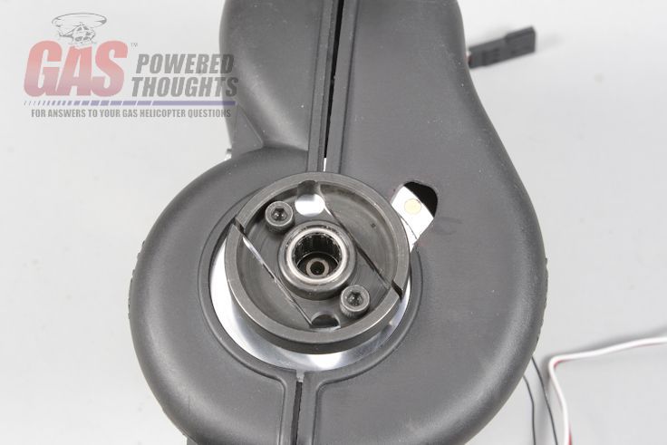 Fan shroud installed on engine The conversion includes bolts for mounting the engine as well as some small shroud spacers. The DFC shroud is slightly too thin for the Trex 600 frame so they must be used properly mount the shroud  Engine mount parts it will be VERY difficult to access the shroud spacers on the right side of the fan shroud, especially on the rear position. I suggest attaching them in advance using adhesive. You CAN install all four of them this way but the ones on the right are the most important. If you do all four, be careful not to get adhesive in the spacer/shroud or you may not be able to ever remove it again Attach shroud spacers Before the engine can be installed, the EI system has to be installed in the frames. The frames have specific cutouts sized for the EI box. Slide the system in through the back of the frames as shown 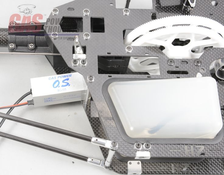 Position EI components Route the EI plug lead between the tank and the lower main shaft bearing block and pull the EI system forward until it can be seated in the hole in the frame 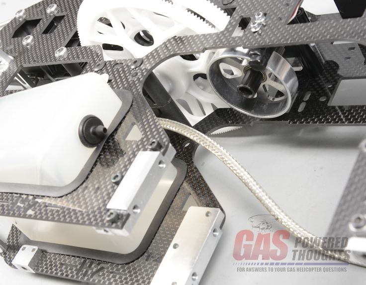 Route EI wiring The EI system "sits" in the frames and is held in place/centered using tie wraps. There are small holes in the frames to allow wrapping them around the EI box and holding it in position as shown 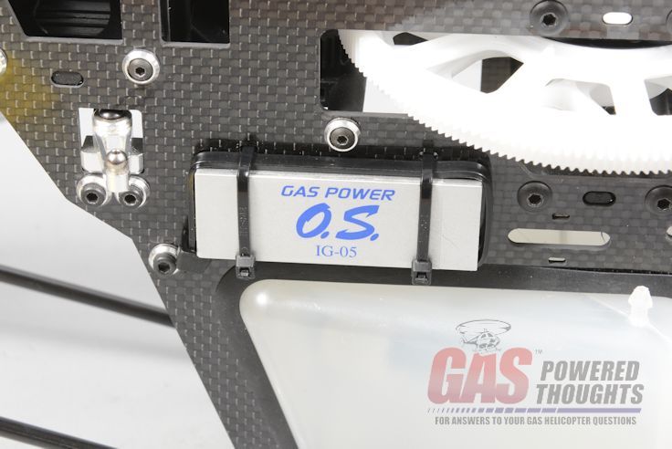 Install EI system Once in place, if you look at the EI system from the back of the frame it should look roughly like this 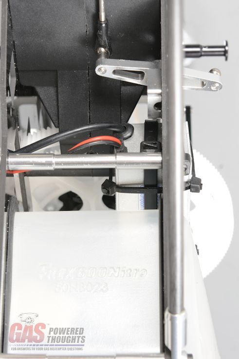 Rear view of EI system NOW you can insert the engine. It WILL go in with the bottom plate/landing gear installed but it is much easier if they are not on the model. You will NOT be able to get the engine back out without removing the lower plate/landing gear It will align normally with the clutch slipping into the bell and over the start shaft 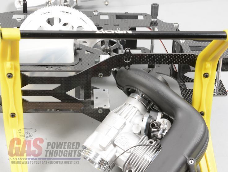 Insert engine Position the engine as shown, making sure the shroud aligns with the mount holes. Be careful to make sure the shroud spacers don't get knocked off 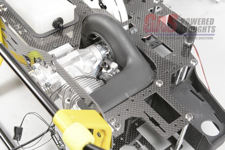 Engine positioned Use the supplied M4 bolts to mount the engine to the engine mount. At this point leave them just slightly loose so the engine can be moved with slight pressure 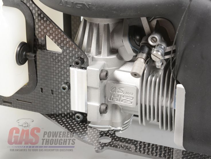 Attach engine Looking from the side, make sure the clutch is fully seated in the clutch bell 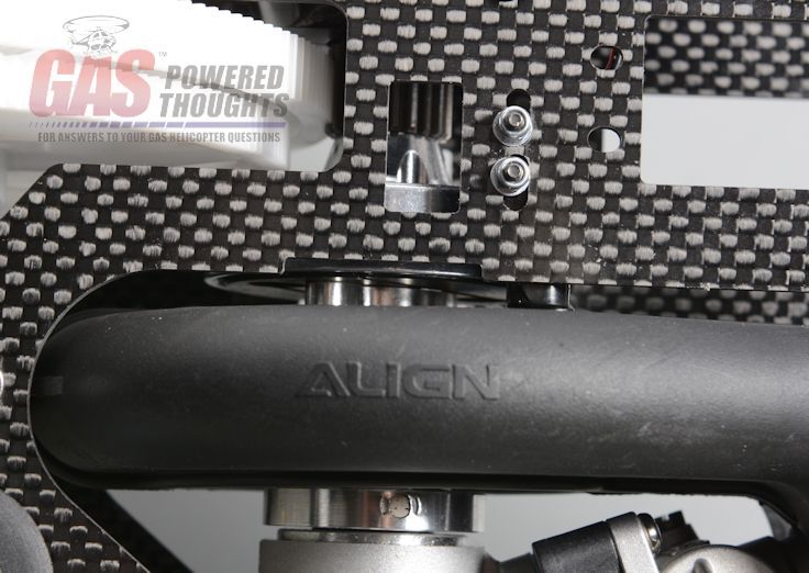 Seat clutch in bell Hold the engine from the back and using a spin starter, spin the engine over. This will self align the engine in the frames Tighten two of the engine mount bolts and then go back and tighten all four using thread lock 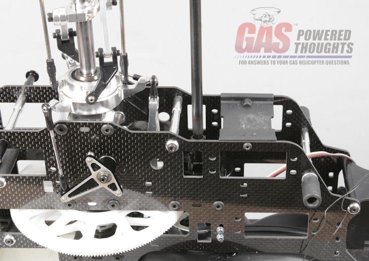 Align engine Install the M3 bolts that secure the fan shroud. Install any shroud spacers that have not already been installed. Position the shroud so that it does not interfere with the fan. Slowly rotate the engine and listen/feel for interfererence. Move the shroud slightly to eliminate any interference Also if you are using an RPM sensor, you might want to set its position now for proper operation with your telemetry system/governor Install fan spacers With the engine installed, now you can install the OS Max fuel pump. The GT15-HZ engine has a large carburetor that contains a pump. The GT15-600 uses a smaller carburetor with an external pump. 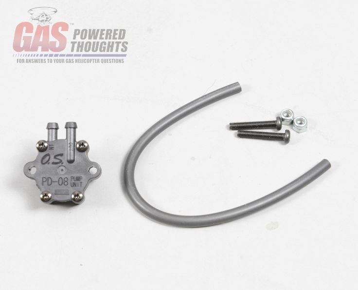 Fuel pump parts This conversion kit includes a specific mount point for the fuel pump, it goes here 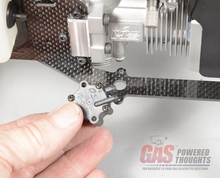 Pump is installed here Use the hardware supplied with the engine to install the fuel pump as shown 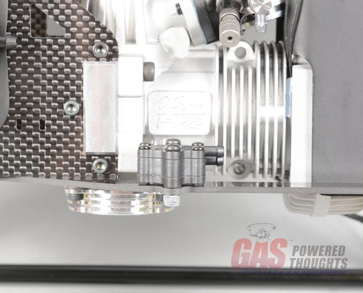 Pump installed The fuel pump vacuum tubing must be cut to size. Cut it at about 10cm (100mm) 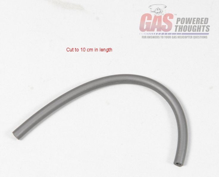 Size fuel pump feed tubing Install the fuel pump tubing as shown. It installes on the nipple on the engine back plate and the small nipple in the center/back of the fuel pump as shown. You may need to lubricate the tubing as it fits tightly 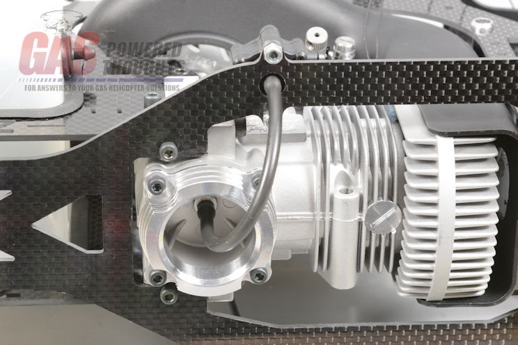 Plumb fuel pump and with that, the engine is installed. Here is how it should look from the left side 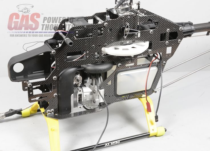 Engine Installed - Left view and from the right side 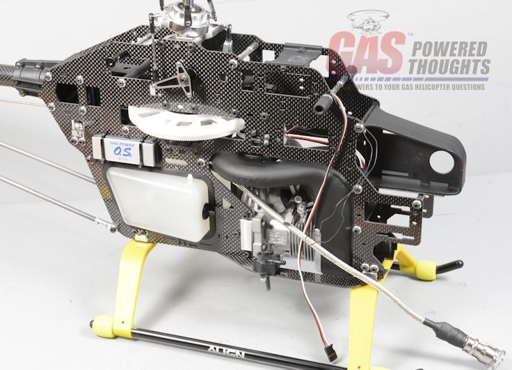 Engine installed - Right View After the electronics are installed, the fuel system will be plumbed and the muffler installed Next Step install electronics Last edited by carey shurley; 02-07-2019 at 05:54 AM.. |
|
|
|
|
06-24-2014, 09:23 PM
|
#4 (permalink) |
|
Registered Users
Thread Starter
Join Date: Apr 2004
|
Install Electronics
Now install the electronics. With the exception of the EI system this is no different than the original Trex layout. Same servos. All the original linkages should work although the throttle rod may need to be adjusted I'm using the GY750 FBL system which has a separate sensor/controller. So I mounted the sensor in the usual gyro position. You can see the Aileron servo installed as well 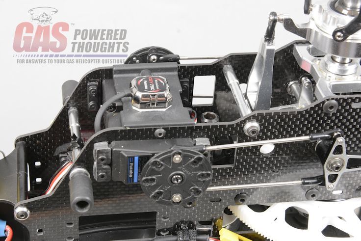 FBL Sensor/Aileron Servo I mounted the FBL controller on the outside of the right frame and the receiver inside the radio "tray" 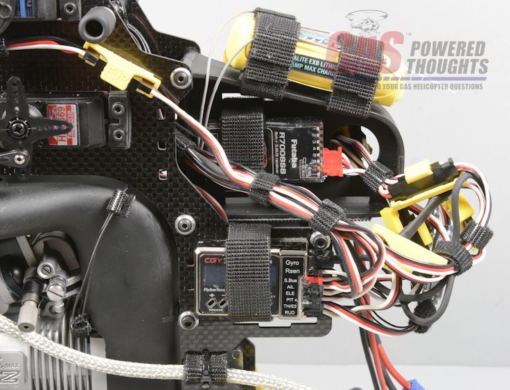 FBL Controller Throttle servo installs from inside the frames 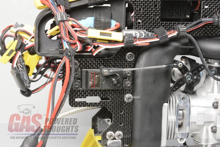 Throttle Servo Here you can see the elevator/pitch servos. OS has added holes along the frame that make it easy to route the wiring and secure it with tie wraps 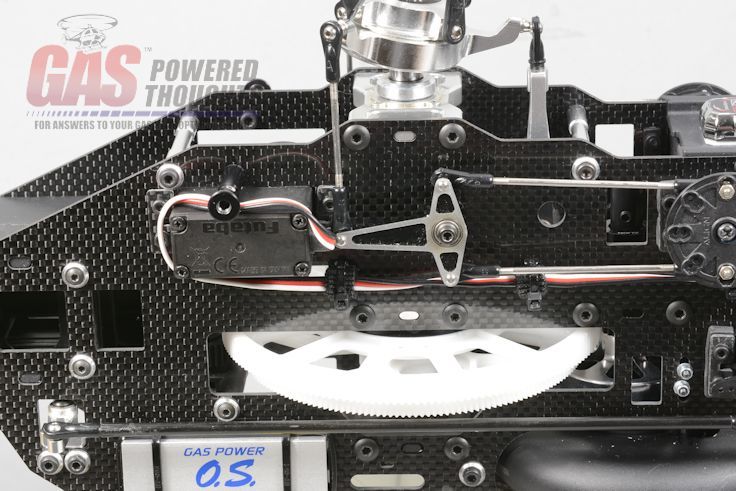 Elevator/Pitch servos Std rudder servo and linkages 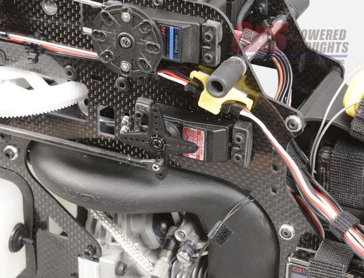 Rudder servo Here's the difference, the EI system needs to be connected. The black sensor wire from the engine connects to the black trigger wire on the EI system. The red wire must go to a power supply. You can use a separate battery or you can just run it off the same battery as everything else I use a Fromeco battery adapter which has an EC3 connector on one side and two std Rx connectors on the other. I plug one into the Rx and the other into the EI system. 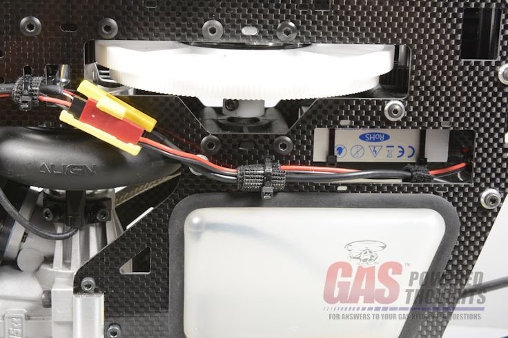 EI wiring I don't use switches, before/after each flight I simply plug/unplug the main battery into the Fromeco adapter 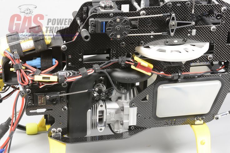 Electronics - Left view Now you can connect all the linkages, power up the system and set up your controls. I set the initial throttle curve to: 13%, 27%, 37%, 47%, 100% and will adjust from there Initial pitch is set to a max of 10 degrees and will adjust as the engine breaks in I'll repeat an earlier note, I wouldn't try to run this engine without a telemetry sensor for temperature that you can set alarms for. This engine will not tolerate extreme overheating. Next Step complete model Last edited by carey shurley; 02-07-2019 at 05:55 AM.. |
|
|
|
|
06-24-2014, 09:38 PM
|
#5 (permalink) |
|
Registered Users
Thread Starter
Join Date: Apr 2004
|
Tank Plumbing, Muffer. Spark Plug, Blades
There are just a few steps left to complete the model The fuel system needs to be completed. Use gasoline proof tubing like Tygon or Viton. I don't recommend neoprene as I've had issues with it splitting You need to connect the fuel tank to the pump. The "inlet" is marked on the pump so run a line from the pump inlet to the fuel outlet on the tank. I'd suggest installing a T fitting here for filling/emptying the tank Now run a line from the pump outlet to the inlet nipple on the carburetor. Finally make up a vent for the tank vent. You need to put a couple of loops in this or fuel will run out if you flip the model. You can also use a one way valve on this if you want although they tend to need more maintenance 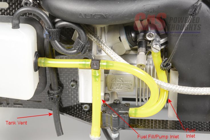 Plumb fuel tank The GT15 engine includes this spark plug made by RCxL. Be careful with it, it is fragile 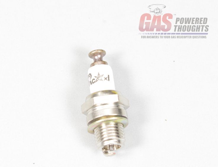 Spark plug The spark plug installs just like a glow plug, just tighten it until it seats fully 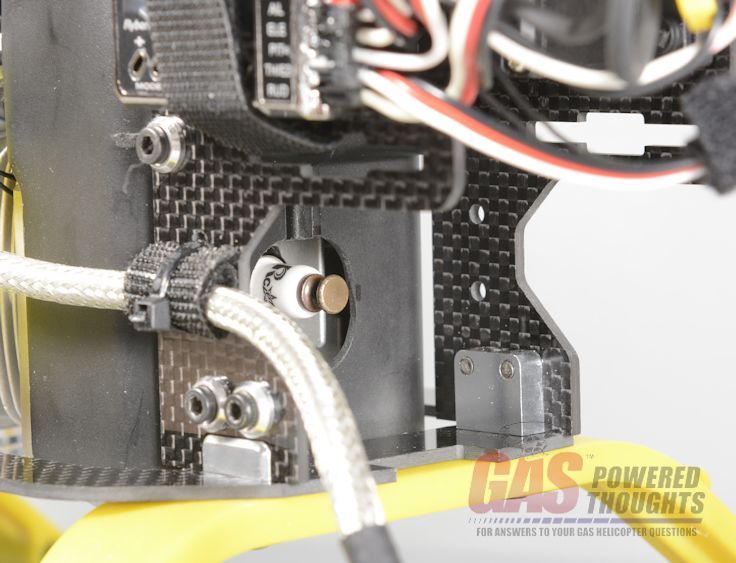 Install Spark plug Now the plug cap goes over the plug. This needs to be pressed on hard to seat. This used to be a major source of problems as if the cap wasn't seated it would arc or back flow through the electronics and cause issues. OS added a spring that extends below the cap and contacts the cylinder head regardless. This should eliminate most of the electronic issues 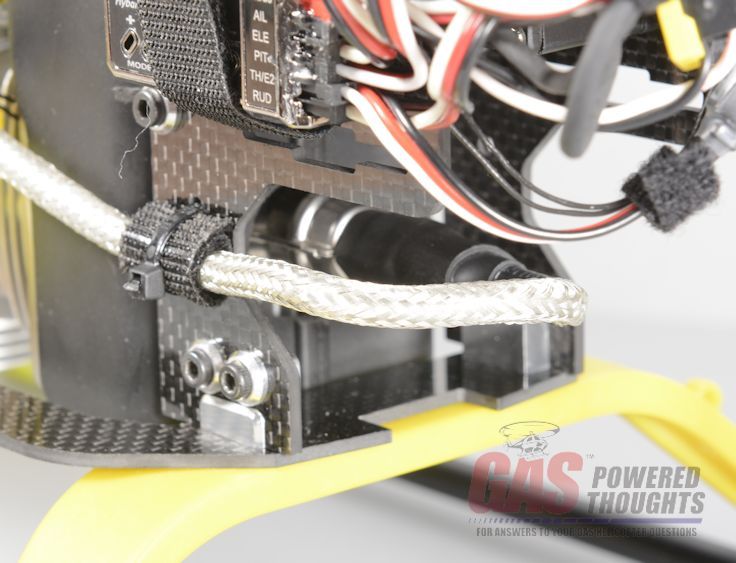 Seat plug cap This engine came with the OS Max Powerboost pipe. Especially designed for this engine, it provides the right amount of back pressure to prevent overheating but remains generally quiet 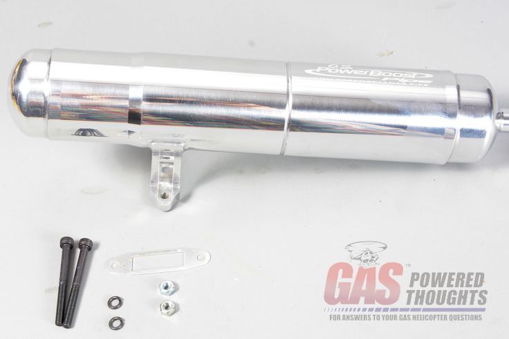 OS Powerboost Pipe The muffler comes with a metal gasket, make sure its in place between the muffler and the cylinder before you install the muffler 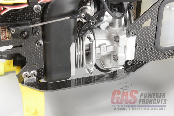 Install muffler gasket Here you can see the muffler installed. It mounts just like the normal OS max muffler with bolts that go through lugs on the cylinder from the intake side of the engine 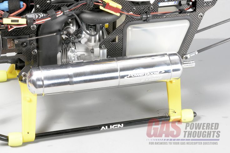 Muffler installed Wrap up the model by installing the rotor blades. I'd suggest no longer than 600mm main blades 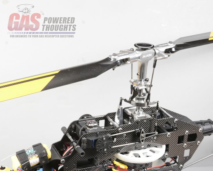 Install rotor blades And thats it for the conversion, its done! 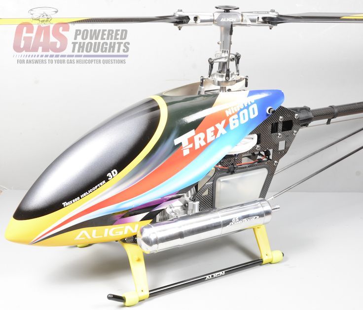 Model completed Next Step Summary Last edited by carey shurley; 02-07-2019 at 05:56 AM.. |
|
|
|
|
06-24-2014, 09:41 PM
|
#6 (permalink) |
|
Registered Users
Thread Starter
Join Date: Apr 2004
|
Summary
When completed the converted model looks only slightly different than the original Trex 600 But the flight times will be completely different now 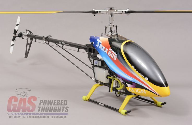 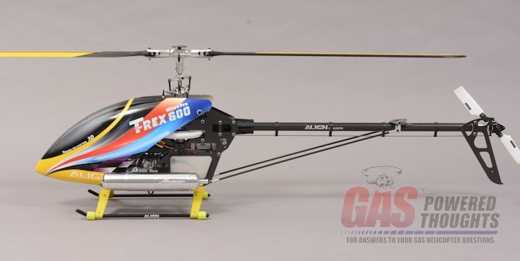 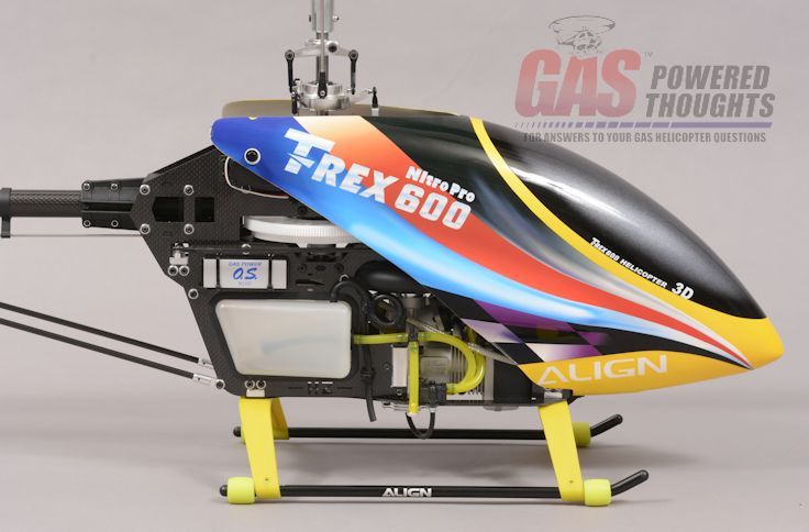 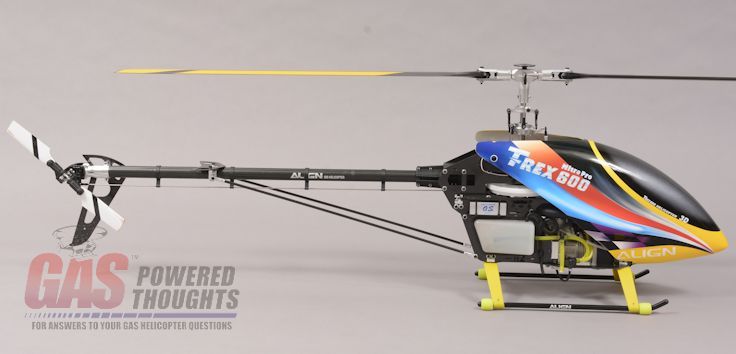 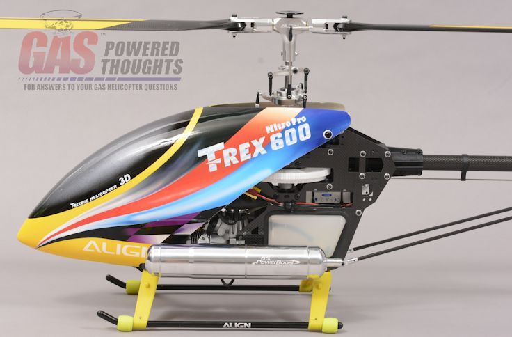 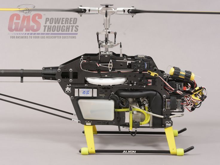  Next Step Flying Last edited by carey shurley; 02-07-2019 at 05:56 AM.. |
|
|
|
|
06-24-2014, 09:42 PM
|
#7 (permalink) |
|
Registered Users
Thread Starter
Join Date: Apr 2004
|
coming soon
|
|
|
|
|
06-24-2014, 11:40 PM
|
#8 (permalink) |
|
Registered Users
Join Date: Oct 2007
|
How hard would it be to convert a 600 E to a 600G?? I so want to do this to one of my 600Es.
Ted
__________________
Ted Schubert I always have fun. Some times are more fun than others. I can't remember half the crap I forgot. |
|
|
|
|
06-25-2014, 06:49 AM
|
#9 (permalink) |
|
Registered Users
Thread Starter
Join Date: Apr 2004
|
Hey Ted
well for sure you'd need the fan hub, clutch, clutch bell and bearing block and a main gear (170T). What I don't know is are the frames the same width between the nitro and electric. If not you'd have to buy a lot of parts the conversion kit states specifically it will convert: T-Rex 600 Nitro Pro T-Rex 600 Nitro V2 (limited edition) T-Rex 600 Nitro DFC |
|
|
|
|
06-25-2014, 09:55 AM
|
#10 (permalink) |
|
Registered Users
Join Date: Jun 2005
Location: Houston TX / Bend Or
|
Carey, after hearing all the problem's with this engine, I'm still waiting to hear from some people that have gotten 5 or 10 gals of fuel through this engine with out eating it's self.
__________________
We had a great country once. You know what made it great? I can. Then the weak came along, the I cants and destroyed it. |
|
|
|
|
06-25-2014, 09:18 PM
|
#11 (permalink) |
|
Registered Users
Join Date: Jan 2010
|
Carey what temperature do you set your alarms at for telemetry? I believe OS states an operating temp of 130c - 266f, but I wasn't able to find a overheating temp.
__________________
XL Power 700v2 Nitro NME - OS 105HZR - Power Tune - Rail 716/106 - Brain2 HD |
|
|
|
|
06-26-2014, 07:48 AM
|
#12 (permalink) |
|
Registered Users
Join Date: Jun 2013
|
on my Zenoah motors I set mine for 365F with the tuned pipe.
__________________
Gasser Mike Team KDE Direct, TRM Power, Byron Fuels, MKS Servos |
|
|
|
|
06-26-2014, 02:22 PM
|
#13 (permalink) |
|
Registered Users
Thread Starter
Join Date: Apr 2004
|
I've just started running this one, I have about a gallon through each of the original HZ engines without any issues
af far as the temps I think it depends on where you measure, right now I'm seeing 140ish temps but its 100 degrees outside here I have learned that a felt clunk won't work with this fuel pump, need to go back and change a couple of steps
__________________
Carey Shurley Proprietor - Gas Powered Helicopters |
|
|
|
|
06-27-2014, 10:02 AM
|
#14 (permalink) |
|
Registered Users
Join Date: Sep 2013
|
Carey, how did you notice that? Because I use this felt clunk as well on my GT15HZ with the walbro carb. I don`t have any issues with it so far. But maybe I am just not sensible enough to notice it. Is the external pump weaker than the internal?
regards Dennis
__________________
SAB Kraken 580, Pyro 600, HOBBYWING Platinum Pro 100A, Brain2 Miniature Aircraft Interceptor 600, OS MAX GT15HZ 2, Brain2, Lynx OXY2, Micro Brain2 Bell 222 with T-Rex 600E chassis, V-Bar |
|
|
|
|
06-27-2014, 04:53 PM
|
#15 (permalink) |
|
Registered Users
Join Date: Jan 2010
|
That is interesting about the felt clunk. I was using the supplied felt clunk with the fourtitude tank, and didn't seem to have any issues with fuel delivery.
What clunk will you be using?
__________________
XL Power 700v2 Nitro NME - OS 105HZR - Power Tune - Rail 716/106 - Brain2 HD |
|
|
|
|
06-27-2014, 05:50 PM
|
#16 (permalink) |
|
Registered Users
Thread Starter
Join Date: Apr 2004
|
I noticed because the pump kept pulling bubbles even with the tank full
So I plumbed a second tank with no clunk............no bubbles replaced the felt clunk with one from a JR GSR model, it worked I'll have to plumb in some sort of filter.............which I hate On the original GT15HZ which had a similar carburetor and NO pump, I saw similar behavior. The current GT15HZ with the walbro doesn't care Once I get the mixture and setup sorted I might try one more time just to make sure but all I changed was the clunk and the behavior changed immediately
__________________
Carey Shurley Proprietor - Gas Powered Helicopters |
|
|
|
|
06-27-2014, 11:20 PM
|
#17 (permalink) |
|
Registered Users
Join Date: Jan 2010
|
That's very interesting. I read your post right before I was about to begin the break in process on the rebuild from OS. I was a little worried as I too have a felt clunk in my tank.
Luckily, I'm at a fun fly and had Mr. Darby look over my helicopter and fired it up on the bench. We didn't notice any bubbles coming out of the pump, so I went ahead and put my 1st tank through the motor. I kept an eye and constantly kept checking for bubbles but I did not notice anything. What is very odd about the situation is I too noticed bubbles coming out of the pump on my first go around with this engine. But I am also running a new pump as my original was lost in shipping.
__________________
XL Power 700v2 Nitro NME - OS 105HZR - Power Tune - Rail 716/106 - Brain2 HD |
|
|
|
|
06-29-2014, 11:30 AM
|
#18 (permalink) |
|
Registered Users
Join Date: Oct 2009
|
Great info on the build! Hope to do this early next year.
__________________
Blade MCP-X Brushless, 300CFX,  , Trex 450 Pro v2, Trex 600 ESP 6s 3GX v.3.1 and KDE head, Rotormast V-22, Futaba 12Z controle!! , Trex 450 Pro v2, Trex 600 ESP 6s 3GX v.3.1 and KDE head, Rotormast V-22, Futaba 12Z controle!!
|
|
|
|
|
|
|
«
Previous Thread
|
Next Thread
»
| Thread Tools | |
| Display Modes | |


 Linear Mode

|
|


