| START HERE |
|
| Register | FAQ | PM | Events | Groups | Blogs | Calendar | Mark Forums Read |
|
|
|
Unregistered
|
||||||


| Skookum Robotics Skookum Robotics SK-360 SK-540 & SK-720 Digital Flybar |
|
|
 |
|
|
LinkBack | Thread Tools | Display Modes |
 04-20-2011, 05:29 PM
|
#41 (permalink) |
|
Join Date: Mar 2007
|
=] please post this on the main page, attention assured!
georgi UK |

|


|
| Sponsored Links | |||
|
Advertisement |
|
||
|
05-04-2011, 09:38 AM
|
#42 (permalink) | |
|
Registered Users
Join Date: Dec 2009
|
Quote:
This is an update to my description above: An upcoming SK-720 firmware update will include Inverted Self Leveling! Whoo-hoo!  See info here for now: https://www.helifreak.com/showthread.php?t=296311
__________________
Jose (Youtube -> Silverexpress01 See also Helifreak Blog) MCPx 76/7 | Trex 250 DFC 667/19 | Hurricane 200 FES 143/7 |
|
|
|
|

|
06-06-2011, 09:14 AM
|
#43 (permalink) |
|
Registered Users
Join Date: Dec 2009
|
A neat tutorial on the implementation of accelerometers and gyros (for the hobbyist).
http://www.instructables.com/id/Acce...Gyro-Tutorial/
__________________
Jose (Youtube -> Silverexpress01 See also Helifreak Blog) MCPx 76/7 | Trex 250 DFC 667/19 | Hurricane 200 FES 143/7 Last edited by Silverexpress01; 06-06-2011 at 10:45 PM.. |
|
|
|
|
06-22-2011, 04:27 PM
|
#44 (permalink) |
|
Registered Users
Join Date: Feb 2011
Location: OR, US
|
Compass 6HV users with SK-720:
Boltor ( latest setup ) - SK-720 with Power Bus, using governor - HW Platinum 70A ESC - Hyperion Phase Sensor (for gov) - DS610 Cyclics, DS650 Tail - Edge 95mm CF tail blades - Western Robotics Hercules Super BEC - Futaba 8FG, with s-bus (using R6203SB FASST Rx) into the SK720 Heathy - SK-720 with powerbus, v 3.02 - Hobbywing 70A ESC - Hyperion Atlas DS20x-SMD Cyclics, DS20x-GCD Tail - Stock dampers - KBDD Extreme edition 96mm tail blades - Western Robotics Hercules Super BEC J0hnny007 - SK-720 with powerbus, v 3.0 - CC ICE 80 HV - JR 8917 HV Cyclics, BLS251 Tail - KBDD Dampeners - KBDD Extreme edition 96mm tail blades - Western Robotics Hercules Super BEC - Western Robotics Titan Dual Step-Down Voltage Regulator Colonny5 - SK-720 with powerbus, v 3.0 - Hobbywing 70A ESC - Hyperion Atlas DS20x-SMD Cyclics, DS20x-GCD Tail - Stock dampers - Stock tail blades - CC BEC Pro Johnjonfenomenon - SK-720 with powerbus, v 3.01 - Hobbywing 70A ESC - Align DS610 Cyclics, DS620 Tail - Edge 623 FBL blades - KBDD lime dampers - KBDD Extreme edition 96mm tail blades - Western Robotics Hercules Super BEC Andy.Kim - SK-720 with powerbus, v 3.02 - CC ICE 80HV - Stock Motor + 11T (Governed at 2300HS) - JR 8917HV @ 8V Cyclics, BLS251 @ 4.8v (WR Step Down) Tail - KBDD Lime Green Dampener - Radix 92mm Tail Blade Castel - SK-720 with powerbus, v 3.02 - Hobbywing 70A ESC, SK-720 Governed - JR 8917HV Cyclics, Outrage BL 9188HV Tail servos - KBDD Lime Green dampers - KBDD tail blades - Western Robotics Hercules Super BEC __________________________________________________ TIPS / ISSUES RESOLVED for reference TAIL Advice for optimal tail setup - (Heathy, KBDD 96mm tail blades, DS20x-GCD Tail servo) Ball at 15mm on tail servo horn and on the inner hole in the tail pitch slider arm. Adjust tail servo travel end points to around 120% on both sides, you will have to remove the tail slider silver spacer on the tail box side. A good starting TX gain is 40%, tail is now rock solid! Bouncing on stops - (Castel, KBDD tail blades, Outrage BL9188HV tail servo) Changed to inner tail pitch arm hole and 15mm servo horn distance from center, no binding anywhere! I set tail pitch at 0* for mid stick and servo travels around 110% on both sides. Headspeed 1850rpm minimum. This fixed bouncing on stops. SK GOVERNOR Pulsing/oscillating throttle with SK governor - (Castel, stock HW ESC, 18.75 motor timing, hyperion sensor) 35% of governor gain is the suggested value to start for using the SK's governor function tuning. Throttle will pulse/oscillate if gain is either too high or too low, it did for me at 15% and at 60%. Trick is reduce gain little by little (1-2%) at a time to find the sweet spot. With stock HW ESC and 18.75 timing it end up being 26% for me, steady RPMs for 1850-2200. Wobbling on spool up with SK Governor - (Castel, Stock HW ESC w/ stock firmware, KBDD Lime Green dampers) The stock ESC does not have a very good soft start. Even though tight, the blades can shift a little on start creating a lot of wobbling during spoolup at low rpms, this goes away as soon as the speed keeps raising. With the default 100% Low Ramp setting for the SK-720 governor the wobble is way more than ideal. You can raise the ramp to 140% to get past this wobbling or the best choice is to update the HW-ESC firmware with the Turnigy version which has an improved soft-start and leave default 100% low ramp.
__________________
Compass 6HV - FBL SK-720 Last edited by georgi UK; 09-25-2011 at 12:02 PM.. Reason: added Bolter's revisions. |
|
|
|
|
09-21-2011, 01:51 PM
|
#45 (permalink) |
|
Registered Users
Join Date: Jul 2011
|
This is a clarification for mounting the TM1000 with the SK720 to allow it to bind:
RED is the positive power lead and the BROWN is the Negative. The ORANGE is the signal line. To provide power and allow the TM1000 to be able to bind, you must cut the orange cable between the SK720 and TM1000 so the TM1000 gets just the positive and negative feeds. Plug the connector into the SK720 with the orange lead cut into one of the open slots (I used IO-C) and you will now be able to bind the TM1000 along with your regular receiver to your transmitter. I did this to be able to monitor the voltage levels in my Trex 450 Pro. I'll post this in a couple relevant threads as I wasn't able to find comprehensive instructions (for a newbie) to guide me through this process. |
|
|
|
|
11-10-2011, 11:09 PM
|
#46 (permalink) | |
|
Registered Users
Join Date: Feb 2010
|
Quote:
__________________
DIABOLO - Spirit goblin 500 Sport-- Spirit |
|
|
|
|
|
11-11-2011, 01:42 PM
|
#47 (permalink) |
|
Join Date: Mar 2007
|
=] it's correct? each cable is carrying 3 connections, its a scheme so it only shows one trace.
__________________
 |
|
|
|
|
11-11-2011, 04:33 PM
|
#48 (permalink) | |
|
Registered Users
Join Date: Feb 2010
|
Quote:
__________________
DIABOLO - Spirit goblin 500 Sport-- Spirit |
|
|
|
|
|
11-14-2011, 12:09 AM
|
#49 (permalink) |
|
Registered Users
Join Date: Jul 2008
|
SK720 Skookum FBL Unit
SK-PW 7 Skookum Power bus OPTIMA 7 HITEC Telemetric RX MUTIGOV PRO Aerospire Governor Used the Optima 7's SPC connector for telemetric battery status monitoring. CH5 Controls both, Cyclic and Gyro Banks. Note that CH3 and CH6 are not as usual (CH3 THRO), I inverted them to give PITCH a higher priority in the Aurora 9. Hope it helps. |
|
|
|
|
12-06-2011, 05:16 AM
|
#50 (permalink) |
|
Registered Users
Join Date: Nov 2010
|
Thanks for the Post. I will be trying this on 600N. I am hoping to us the Self level on 600N
|
|
|
|
|
12-06-2011, 05:20 AM
|
#51 (permalink) |
|
Registered Users
Join Date: Nov 2010
|
I will be using your method,hoping it will keep my vibe levels low enough to use the self level on my 600N. Thanks for the post
|
|
|
|
|
12-08-2011, 08:08 AM
|
#52 (permalink) | |
|
Registered Users
Join Date: Mar 2011
Location: West Seattle, WA, USA
|
Quote:
__________________
14S Specter 700 V2 NME/Tron 7/Kraken; 8S Tron Dnamic; 7S Kraken 580; 6S Buddy 380 KSE VBCE/Neo/EVO, Jeti/Spirit, YGE "T" ESCs; LiFePO4 field charging batteries Sims on Mac: Heli-X, neXt, AccuRC, Phoenix, AeroFly RC7 Ultimate Amain Team Pilot |
|
|
|
|
|
12-08-2011, 11:42 AM
|
#53 (permalink) | |
|
Registered Users
Join Date: Oct 2010
|
Quote:
 |
|
|
|
|
|
12-08-2011, 12:52 PM
|
#54 (permalink) | |
|
Registered Users
Join Date: Mar 2011
Location: West Seattle, WA, USA
|
Quote:
Photo1: BEC wires connected to Power BUS red and black wires. This would involve sacrificing the BEC servo connectors and some soldering, but the Power Bus empty slots would remain empty for future expansions, i.e. GPS. Photo2: Power BUS red and black wires capped. BEC wires connected to Power BUS slots PWR-HV and PWR-LV. The problem that I have with this setup is that PWR-LV slot is isolated from the servos on the PWR-HV side of the grid. Only PWR-HV would be powering the servos. Photo3: Power BUS red and black wires capped. BEC wires connected to BUS C and BUS D slots. I believe that this should work, but this setup would not leave me with ability to add future expansions. Photo4: Power BUS red and black wires capped. BEC wires connected to BUS C and PWR-HV slots. I believe that this should work, and would leave BUS D slot free for a future expansion. Please, critique. Thanks.
__________________
14S Specter 700 V2 NME/Tron 7/Kraken; 8S Tron Dnamic; 7S Kraken 580; 6S Buddy 380 KSE VBCE/Neo/EVO, Jeti/Spirit, YGE "T" ESCs; LiFePO4 field charging batteries Sims on Mac: Heli-X, neXt, AccuRC, Phoenix, AeroFly RC7 Ultimate Amain Team Pilot |
|
|
|
|
|
12-08-2011, 01:03 PM
|
#55 (permalink) | |
|
Registered Users
Join Date: Oct 2010
|
Quote:
Basically the power bus is simply 2 power rails with servo signals distributed between them. If you only wish to use one voltage for your R/C equipment then you connect these 2 power rails into one rail by connecting the pins shown with the red wire in the drawing above. This makes the powerbus into one big common power rail, now you can plug your BEC into the big wires or into any open servo terminal. |
|
|
|
|
|
12-08-2011, 01:28 PM
|
#56 (permalink) |
|
Join Date: Mar 2007
|
=] does the vid help??! =
[ame]http://www.youtube.com/watch?v=Dpa_34nmLsY&feature=player_embedded[/ame]
__________________
|
|
|
|
|
12-08-2011, 02:20 PM
|
#57 (permalink) |
|
Registered Users
Join Date: Mar 2011
Location: West Seattle, WA, USA
|
Thanks. I did see the video before. However, the video uses a 2S Lipo as a power source, and only mentions the BEC for connection between the high and low voltage system.
It seems that in my case, I should connect the BEC to the red and black Power BUS wires, where the 2S Lipo would otherwise connect. One concern that I have is that the SK-720 would only be powered by Power BUS A via the tiny current-limiting wires connected to the Tail slot of the SK-720. The SK-720 would in turn have to power the AR8000 receiver and the TM1000 telemetry. I hope that there is enough current via the tiny wires from Power BUS A to power all of these electronics.
__________________
14S Specter 700 V2 NME/Tron 7/Kraken; 8S Tron Dnamic; 7S Kraken 580; 6S Buddy 380 KSE VBCE/Neo/EVO, Jeti/Spirit, YGE "T" ESCs; LiFePO4 field charging batteries Sims on Mac: Heli-X, neXt, AccuRC, Phoenix, AeroFly RC7 Ultimate Amain Team Pilot |
|
|
|
|
12-08-2011, 03:12 PM
|
#58 (permalink) |
|
Join Date: Mar 2007
|
=] the demand is on the servo side of the bus, you need to run a playback log to see the voltage drops here.
__________________
|
|
|
|
|
12-08-2011, 04:23 PM
|
#59 (permalink) |
|
Registered Users
|
Here is my main power harness:
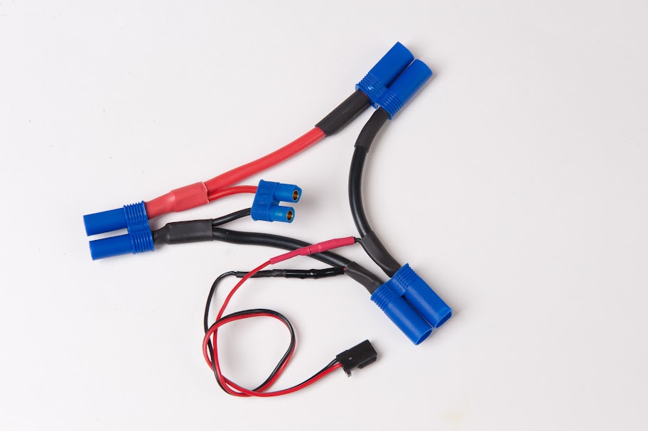 Two right most EC5 connectors are for the 5S LIPOs (in series for 10S power) Servo type wire is to feed the SPC on the Optima 7 (5S = 18.5 volts nominal) EC3 connector feeds 10S to BEC Left EC5 feed 10S to the ESC
__________________
Futaba 14SG, Synergy E5, Furion 6, Beam E4(v1) FBL, CGY750, Skookum |
|
|
|

|
|
|
«
Previous Thread
|
Next Thread
»
| Thread Tools | |
| Display Modes | |


 Linear Mode

|
|


