| START HERE |
|
| Register | FAQ | PM | Events | Groups | Blogs | Calendar | Mark Forums Read |
|
|
|
Unregistered
|
||||||


| Finless Bob's Helifreak Tech Room Finless Bob's Helifreak Tech Room - Tips and how-To Videos |
|
|
 1Likes
 |
|
|
LinkBack | Thread Tools | Display Modes |
 03-08-2008, 07:44 PM
|
#1 (permalink) |
|
The Capi
|
**************************************************
BACKGROUND ************************************************** First I will provide some background about myself so you can better understand where this is coming from. About 17 months ago I stumbled across Bob White's (Finless) great video series, I stayed up until all hours of the night watching all of his builds like a kid at christmas (this was back when there wasn't a build series for every electric heli on the market). Well i decided right there and then that i must have one myself, i spent the next 3 months doing my research and deciding if i really wanted a new hobby. Boxing day rolled around (day after christmas for you americans) and i pulled the trigger and bought an Align Trex 450se v1. The rest is history. I owe all the fun (and my lack of a financial future) to Bob and Will for this great site so this is my way of beginning to pay it back (Thanks for the chat-room guys). After graduating from my undergraduate degree in Electrical engineering i was accepted into graduate studies as a Masters of Applied Science In Electrical Engineering student, I quickly transferred to the Ph.D program as i felt another 6 years in school would have driven me insane (Some would debate I was already insane to begin with). My area of research is in Analog CMOS integrated circuit design with a specialty in Phase-locked loops, this means I am by no means an expert on Power electronics or motors ( If you find any mistakes please PM me and I will correct them). I've had the opportunity to teach classes and take great joy in educating others, so I will do my best to educate anyone interested in brushless motors and the electronic speed controllers that we use in helis. I will try to keep the information consumable by the general public and avoid math as much as possible (you didn't think you would get away scot clean did you ?). ************************************************** Introduction ************************************************** With the explosive growth of the electric powered helicopter most of us have become familiar or even own many brushless motors and brushless electronic speed controllers, but very few of us understand how they function. With a better understanding of how both the motor and esc functions a person is better able to setup, tune or diagnose problems when they arise. A simple search of the forums will prove this fact, many questions are frequently asked and the same answers provided. This tutorial will cover the following topics ** Magnets and Electromagnets ** Brushed Motors ** Brushless Motors ** Outrunner vs Inrunner ** Back electromotive force (EMF) ** Electronic Speed Controllers ** ESC Governor mode Well dust off your pencils and take a seat we are about to get started ************************************************** Magnets and Electromagnets ************************************************** A magnet is a material that generates a magnetic field. A magnetic field can be viewed only through its interaction with other materials. One method is something we have all seen back in school (for those of us that can remember that far back  The magnet clearly has a north "N" and south "S" pole at opposite ends. The basic rules of magnetic poles is that opposite poles attract and like poles repel each other. If you take two fridge magnets and try to push them together you can feel the repulse force. These magnets are referred to as permanent magnets as they will retain their magnetic properties indefinitely. Another type of magnet is called an electromagnet, this type of magnet produces a magnetic field by using electricity. By passing an electric current through a conductor we produce a magnet field as shown below. http://upload.wikimedia.org/wikipedi...omagnetism.svg B is the magnetic field that surrounds the conductor. The magnetic field does not move, the arrows only show the direction of the field (right hand rule - take your right hand, point your thumb in the direction of the electric current, your fingers will point in the direction of the resulting magnetic field) . The magnetic field creates a "N" and "S" pole making it a magnet as long as the current continues to flow. The higher the current passing through the conductor the stronger the magnetic field that is produced. Even for very large amounts of current the magnetic field will be small. We can increase the strength of the magnetic field by having more current carrying conductors running parallel to the one we already have. Having multiple conductors beside each other will result in the addition of the magnetic fields, this is most easily accomplished by wrapping the one wire into a coil. Coiling wire creates what is known as an inductor and is shown below  There is no difference between the magnetic field and poles created by the permanent magnetic and the electromagnet, we can use their poles to attract or repel eachother just like our fridge magnets. ************************************************** Brushed Motors ************************************************** Motors harness the attractive and repulsive forces that exist in magnets and converts them into a rotation. Motors consist of two major parts, a stator and a rotor. The stator as the name implies is the static part of the motor and doesn't move, this is usually made by an electromagnet (just a large coil of wires). The rotor is the moving or rotating part (engineers aren't particularly creative when it comes to naming things) and consists usually of a permanent magnet and connects to the motor shaft that turns. A simple motor is shown below 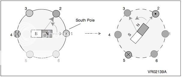 The permanent magnet in the middle is the rotor and consists of a "N" and a "S" pole. The circles labelled 1,2,3,4,5,6 are representations of the coiled wires making up the stator. If we control the stator coils in pairs we can create a electromagnet with a "N" on one side of the motor and a "S" on the other side (If we pass current in the opposite direction in one coil it's pole will be the opposite of the other coil). When the rotor's poles are close to the stator poles there will be an attraction if the poles are different or will repel eachother if the poles are the same. Since the rotor is pinned at the middle the only way it can be repelled or attracted is to rotate. Let's assume we applied current to the "1" stator coil such that it created "N" poles, this will cause the rotor to be repelled as indicated by the arrow. The rotor will now be aligned with the 2,5 coils. If we redirect the current from the 1,3 coils to the 2,5 coils we can again repel the rotor as shown in the next picture. the next step would be to redirect the current from the 2,5 coils to the 3,6 coils. If we continue this process the rotor will continue to turn !! Brushed and brushless motors work on this same exact principle. How the current is redirected between the stator coils is where the brushed and brushless motor depart company. The brushed motor redirects the current to the next pair of coils by mechanical means. it has something called a commutator, the job of the commutator is to connect the external motor wires to the next set of coils by using a conductive brush as shown below.  ************************************************** Brushless Motors ************************************************** A brushless motor works on the same principle as the brushed motor but instead of using a mechanical commutator to redirect the current to the coils in order we use an electronic commutator. By applying a voltage or current to the winding at the proper timing we can replicate the commutator and turn the rotor . The motor and esc have three wires connected to each other forming what is known as a 3-phase motor. Each phase will be connected to a pair of windings. Lets assume phase-A will connect to the 1,4 coils , phase-B will connect to the 2,5 coils and phase-C will connect to 3,6 coils. The coils will be wires into a "Y" connect as shown below 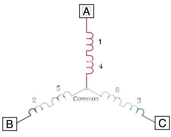 The point at which all the 3 phases connect is known as the neutral point. Each coil pair will be wound in the opposite direction of each other, which will cause one to create a "N" pole and the other a "S" pole when current passes through that phase. So what the heck is a 6-pole motor ?!?!?! Well lets look at an example. The 430XL has a 9 pole stator (count the number of coils !) The 430XL has a 6 pole rotor (count the magnets on the part on the right, yes the case is moving NOT the part on the left) (Pictures are from Iceman33's 430XL bearing replacement thread at https://www.helifreak.com/showthread.php?t=53511) So far we have learned that we need to turn on each pair of stator coils when the rotor's magnet is near so we can use the attractive or repulsive forces of the magnets. What exactly does turning a coil on mean ? Applying a current to the coils turns it on and will create a magnetic field, the intensity of that magnetic field will determine how much force it will attract or repel the rotor magnets. The motor torque is given by the equation (sorry can't avoid this) Motor torque = constant * rotor flux * current in the coils The constant and rotor flux will be fixed by the mechanical design of the motor so we only have to worry about the current. This is why when you use full collective and the motor requires motor torque the motor draws a lot of current. Another important formula is the power of the motor given by Motor power = torque * angular speed of the motor This formula tells us that we can't have high speed and high torque at the same time (we will get to why this is later) !! Let's get back to turning the windings on. The easiest way to apply the current that flows through the stator coils is to apply a voltage to the coils as shown below.  (image from SPEEDY-BL) Each stator has the voltage applied for 1/3 of the cycle (120degrees), one after another they are turned on then off. As the voltage on the coil is applied a current flows which will create a magnetic field, as the voltage is turned off the magnetic field collapses. As the magnetic field in one phase collapses the next phase field is created, this results in a magnetic field that rotates around the stator. The rotor is forced to rotate with the stator magnetic field (This is why changing two of the phases will get the motor to turn the motor the other way, the feild will rotate in the other direction). We will worry about how to control the speed of the motor later. ************************************************** Outrunner vs Inrunner ************************************************** So what is all this talk about outrunners and inrunner ?? While the electromagnet (the coiled wires) will always need a fixed electrical connection outside the motor it will ALWAYS have to remain fixed and thus will always be the stator. That leaves only the permanent magnets as the rotor. If the stator is on the inside of the motor surrounded by the rotating magnets the motor is an OUTRUNNER as shown below (just like the 430XL) https://www.torcman.de/peterslrk/LRK_in_action.gif If the moving rotor is on the inside surrounded by the fixed stators then the motor is an INRUNNER as shown below https://www.speedy-bl.com/speedy-bldc.gif An outrunner produces lower RPMs but is able to produce higher torque. An Inrunner is the opposite of an outrunner in that it can produce higher RPM but in doing so it trades off torque. ************************************************** Back electromotive force (EMF) ************************************************** Just as when we apply voltage to get the rotor to turn the opposite occurs too. The turning of the rotor produces a voltage ! The voltage produced in the windings opposes the applied voltage. We can model this EMF voltage as a voltage in series with the phase. The current in the winding is the difference between the applied voltage and the back EMF voltage divided by the winding resistance and inductance. The back EMF voltage is given by the formula Back EMF Voltage = Number of windings per phase * Length of the rotor * radius of rotor * Rotor magnetic field density * angular velocity ALL of the parameters but the angular velocity are fixed by the mechanical design of the motor. Its clear that as the rotor turns faster the back EMF voltage will increase. The increase in the back EMF voltage will mean a decrease in the phase current. As the phase current decreases so to does the motor's torque. What this implies is that you can't have high torque and high speed at the same time ( I promised i would get back to this). The back EMF voltage can also be VERY useful. How do we know when to turn the phase voltage on ?? We want the phase voltage to be turned on when the rotor is in the right position. But how the heck do we know when the rotor is in the right position ??? There is two ways to determine the position of the rotor, the first is with a hall sensor. The 2nd method is the so called "sensorless brushless motor" which uses the back EMF voltage to determine the position of the rotor. ************************************************** Electronic Speed Controller ************************************************** The ESC has many functions to perform. the first function is to maintain the proper timing of the phase voltages. The phase voltages have to turn on for 1/3 of the motor cycle. As the motor turns faster and faster the cycle becomes shorter (the rotor leaves the stator's pole quicker), the esc's job is to provide the correct timing. The esc uses the back EMF voltage to determine the position of the rotor and turns on the next phase at the appropriate time. Without the correct timing the phase voltages can be applied at the wrong time causing the motor to malfunction. This problem is most pronounced during start up, at which time the motor is turning so slow that the back EMF voltage is too low to detect. Since only one of the phases is on at any given time one of the unused stators can be monitors for back EMF voltage. Well if the esc gets its timing from the motor itself how the heck does the esc control the speed of the motor ?!?! Well this is where it gets a little tricky. First we must learn about pulse width modulation. PWM is the modulation of a fixed voltage into on and off pulses. If you turn the voltage on for half the time and turn it off for the other half the average voltage will be half of the fixed voltage. The modulation is linear and given by the formula Average Voltage = Fixed voltage * Time on / ( time one + time off) An example of PWM modulation is shown below  By modulating the voltage during the phase's 1/3 part of the cycle we can control the average voltage on the winding as shown below  (image from SPEEDY-BL) The average voltage controls the speed of the motor, the motor's KV rating is the number of turns per volt unloaded. ************************************************** ESC Governor mode ************************************************** The governor function built into modern esc seems to be greatly misunderstood so i will briefly describe how it functions here. We have already learned that when the rotor turns it produces a back EMF voltage on the phase windings, and we can use one of the unused phase windings to keep track of the position of the rotor. If we know the position of the rotor we can measure how fast the motor is turning ! When the heli demands a higher torque (due to something like a lot of blade pitch) the speed of the motor will drop because the motor power will be constant. To maintain a the same speed with the higher torque we must increase the power to the motor. To increase the power to the motor we increase the PWM modulation so the Time on is higher then it was before. If the PWM signal is already at 100% (always on) then the esc has no way of increasing the motor's power. To provide the ability to increase the motor power we must run the throttle at a low enough setting such that it can increase the PWM during times of high torque .
__________________
Spreading capibara awareness since 2006 Last edited by Skiddz; 11-10-2019 at 01:24 PM.. |

|


|
| Sponsored Links | |||
|
Advertisement |
|
||
|
03-08-2008, 10:24 PM
|
#2 (permalink) |
|
Registered Users
|
Very nice writeup.
Thanks for giving back Take care Rune |
|
|
|
|
03-08-2008, 10:47 PM
|
#3 (permalink) |
|
Registered Users
Join Date: Jun 2006
|
Thanks! I never really knew how EMF and PWM worked.

__________________
Steve Trex 450 Pro = MSH Prôtos = Logo 600 |
|
|
|
|
03-08-2008, 11:00 PM
|
#4 (permalink) |
|
Registered Users
|
Thankyou, that was quite the explanation. I just thought that as long as it works, I don't need to know how it works. But now I understand what poles, stator, etc. are! Thanks again
 |
|
|
|
|
03-09-2008, 11:04 AM
|
#5 (permalink) |
|
Registered User
|
WOW!! Thanks!!
__________________
William James Crazy wife still trying to kill me.  |
|
|
|
|
03-09-2008, 11:25 AM
|
#6 (permalink) |
|
Team Taco VP
|
This is some great info! Nice job HFG.....
Bob
__________________
"Don't Taco My Pack Dude!"  NEW Video Link -> Safety Video #1 Video Link -> CAUTION using powerful tools! Video Link -> How to CRASH TWICE in one flight! Video Link -> Don't Taco! |
|
|
|
|
03-09-2008, 06:46 PM
|
#7 (permalink) |
|
The Capi
Thread Starter

|
Upon pinecone's insistence (
__________________
Spreading capibara awareness since 2006 Last edited by DominicD; 03-09-2008 at 07:47 PM.. |
|
|
|
|
03-09-2008, 07:46 PM
|
#8 (permalink) |
|
Registered Users
|
Nice writeup. I never really knew how a brushless motor worked. Well done
__________________
Dirty B - LARCC/RRAMS/MARCS
FLEET: Blade 150S |
|
|
|
|
03-09-2008, 08:00 PM
|
#9 (permalink) |
|
Registered Users
|
Worthy of Sticky status in my book.
__________________
Gravity Sucks... T-Rex 600E CF, T-Rex 500 CF T-Rex 450 SEV2, T-Rex 450 SEV2 6s1p, Lama V4 DX7² Discover Card |
|
|
|
|
03-10-2008, 09:48 AM
|
#10 (permalink) |
|
Registered Users
|
Oooooouuuuuucccccccchhhhhhhhhhhh! My head hurts now. That was an incredible read. I know i missed (= didn't sink in) some things so i am going to read it again. Nice work.
__________________
- Mike - MINI TITAN - DX7, AR6100, GY401 w/3400G, TP 2100 TREX 500 - DX7, AR7000, JR 3650Z's, GY401 w/9254 |
|
|
|
|
03-10-2008, 10:03 PM
|
#11 (permalink) |
|
Registered Users
|
Thanks Capi, very informative, should be worthy of a sticky
__________________
Trex 500 ESP Future Fusion 50 FBL AMA #913061 "No you can't fly it" |
|
|
|
|
03-10-2008, 11:14 PM
|
#12 (permalink) |
|
Team Taco VP
|
This is such good info that it must be a STICKY!
HFG... It's up to you to manage this posy Bob
__________________
"Don't Taco My Pack Dude!" NEW Video Link -> Safety Video #1 Video Link -> CAUTION using powerful tools! Video Link -> How to CRASH TWICE in one flight! Video Link -> Don't Taco! |
|
|
|
|
03-11-2008, 01:32 AM
|
#13 (permalink) |
|
Registered Users
|
So, I have a 450XL motor. when the pinion turns, the outer case does not.
Is there an inner case with the magnets which rotates around fixed stators? I thought that the outer case of an outrunner would spin, scary though that may be, and it thereby provided a cooling benefit. Wrong again? thx Jim
__________________
PRÔTOS 500 Plastic, Logo 550SX/600SX, PRÔTOS Max2 up and flying! Team MSH USA, Team Cyclone, Team Xnova |
|
|
|
|
03-11-2008, 01:47 AM
|
#14 (permalink) |
|
Registered Users
|
Yes with an outrunner the outer case of the motor spins.
I believe the 430XL is an inrunner motor. Capi can smack me for spreading mis-information if I'm wrong.
__________________
Dirty B - LARCC/RRAMS/MARCS
FLEET: Blade 150S |
|
|
|
|
03-11-2008, 02:01 AM
|
#15 (permalink) |
|
Team Taco CEO
Join Date: Oct 2006
|
No, the 430XL is called a "Canned" Outrunner (as well as all the Align motors for helis). It's constructed the same as other outrunners, except it has an added shell to cover the spinning rotor.
P.S. Nice Job HFG. When I have a chance, I'll o-scope out different motors and ESCs and see if there are any differences in the waveforms. I think on some, the PWM will be a varying PWM so that the "average" voltage will be like a sine wave.
__________________
Kevin Don't Taco My Pack, Bro! , Why crash when you can POUND it! |
|
|
|
|
03-11-2008, 07:35 AM
|
#16 (permalink) |
|
The Capi
Thread Starter
|
Fireup is correct. The 430XL is an outrunner. The 430XL has a moving rotor that surrounds the inner stator making it an outrunner. The 430XL has a blue coloured can around the stator that doesn't turn which makes it looks like a inrunner because the user won't see a spinning can.
__________________
Spreading capibara awareness since 2006 |
|
|
|
|
03-11-2008, 10:19 AM
|
#17 (permalink) |
|
The Capi
Thread Starter
|
Hey Fireup while it's possible i very much doubt you will see any sine waves on any esc we use. Without dual rails we can't even use the most basic of stepping to approximate a sine wave. The only other approach is to use the H-bridge as a class B amp but then the power dissipated by the esc will be HUGE and wash out any advantage that the sin waves would have had on the motor itself.
__________________
Spreading capibara awareness since 2006 |
|
|
|
|
03-11-2008, 10:52 AM
|
#18 (permalink) |
|
The Capi
Thread Starter
|
I have added a littlel section about Outrunners vs Inrunners, hope this clears things up abit.
__________________
Spreading capibara awareness since 2006 |
|
|
|
|
03-13-2008, 07:50 AM
|
#19 (permalink) |
|
Registered Users
Join Date: Sep 2006
|
HFG and I have been having an ongoing PM conversation.
The diagram of the motor in the Brushed Motor section is actually a Brushless Motor. In a brushed motor, the brushes are need since the coils are rotating and yuo need to get the power to them. So the coils are on the shaft that turns, and the brushes work like the next diagram (red and blue rotating commutator). Brushed Motor: The concept of the motors are pretty much the same, changing the energized coils to push/pull the permanent magnets around. The difference is that a brushless motor needs the siwtching of the coils to be controlled outside the motor. Brushed motors control their own switching. On 3 phase AC motors, like many large pieces of machine equipment, they use the 3 phases to energize the coils in sequence. Works well, but only a single speed that is a steady as the power line frequency (which in the US is very stable). About the only place I have seen outrunner motors is model aircraft and computer disk drives. In disk drives they are used because they can produce enough torque in a very thin package. In models they are also used for the higher torque allowing direct drive of larger props or more reasonable gearing for things like helis. In GENERAL, an outrunner will produce more torque and less Kv (RPM per volt) than inrunners. But there is now a significant amount of overlap for lower Kv inrunners and high Kv outrunners.
__________________
Terry AMA#47402, IRCHA # 3395 Blade CP "Pro", Trex 450SE, PiccoZ, Quick of Japan EP8v2 EX, Hurricane 550, Hurricane 200, JR Vibe 50, Blade mCX, Bergen Intrepid Gasser, Pantera 50, Blade mSR, Novus CP |
|
|
|
|
|
|
«
Previous Thread
|
Next Thread
»
| Thread Tools | |
| Display Modes | |


 Linear Mode

|
|


