| START HERE |
|
| Register | FAQ | PM | Events | Groups | Blogs | Calendar | Mark Forums Read |
|
|
|
Unregistered
|
||||||


| Gas Powered Thoughts Advice for Gas Helicopter Success from Carey Shurley |
|
|
 |
|
|
LinkBack | Thread Tools | Display Modes |
 09-13-2012, 10:10 PM
|
#1 (permalink) |
|
Registered Users
Join Date: Apr 2004
|
 Model shown with optional components Last edited by carey shurley; 11-04-2012 at 03:58 PM.. |

|


|
| Sponsored Links | |||
|
Advertisement |
|
||
|
09-14-2012, 05:14 AM
|
#2 (permalink) |
|
Registered Users
Thread Starter

Join Date: Apr 2004
|
This build thread is for the V2 version of the Radikal 30 so I want to start off by highlighting whats different between them. Some of the changes are very obvious and some of them are more subtle. So lets take a look at them
Canopy Lets start with some of the most obvious things, first off the canopy. The Radikal 30 started off with an all white canopy that used colorful decals. I rather liked the look of that but it did require manually installing the decals. It was later replaced with the current one that is red and yellow (not my personal favorite). Then they made some optional one like the one on the left, which is known as the "california".  Radikal 30 California canopy on left - V2 canopy on right Now for the V2 they have introduced this version which is identical is size/shape to the previous fiberglass canopies but as you can see its colored black and yellow with silver lettered highlights.  Radikal 30 V2 canopy Landing Gear next the landing gear is different. The original Radikal (on the left) used typical plastic landing gear. Although durable they were heavy and a lot of the team guys replaced them with the much lighter ones from the NX. 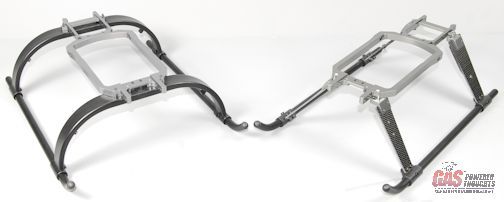 Radikal LG on left - V2 on right So now they've introduced graphite landing gear struts. Although not a new idea, I think the Stratus had this first its become very popular on some other models. They are a little over 2oz lighter than the original and use 4mm mount bolts. the original assembly weighs 12.3 oz and the V2 assembly weighs 10 oz as shown. 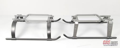 Side view of Landing gear compared another change is that the carbon struts are attached using 4mm bolts as compared to the original 3mm bolts. This requires a different landing gear/motor mount 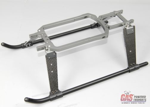 New engine/landing gear mount for 4mm attachment bolts The struts and skids can all be replaced as separate pieces and bolt together. The rear struts have graphite doublers since they support the bulk of the models weight. Unlike a lot of other models that use graphite gear, these have a fair amount of flex in them so the model should not be as prone to bounce off the ground on hard landings. You can also see in this photo that the struts can be slightly repositioned forwards or backwards to account for minor CG changes. 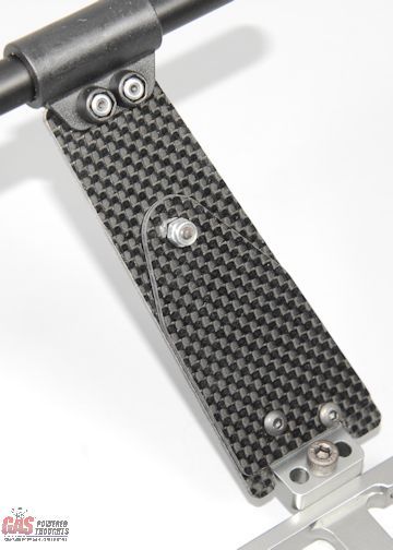 Rear landing gear struts have graphite doublers Rotor Head Its still available in both Flybar or Flybarless versions. I'll be building the FBL version which you can see here. All metal with the swash drivers built into the head block for fixed alignment. This uses the trouble free control rod setup as opposed to a DFC style control system found on some other models. 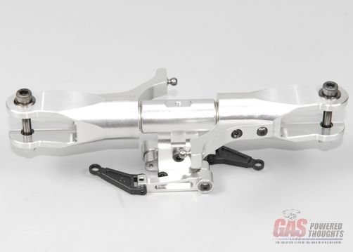 Radikal 30 FBL Rotorhead Rear Gyro Mount Moving towards the rear of the model, there is a gyro plate that can be mounted on top of the front t/r transmission so you can easily mount the gyro there if you want for less vibration feedback into the unit. The belt drive version has always had one of these but the tube drive version has not. Rear gyro mount attaches to tail boom mount Tail Rotor There are a LOT of differences here. The entire T/R transmission is different, now almost all metal with metal helical cut gears. The pitch control mechanism is metal and the blade grips are metal as well. This has been optional for a while but now its included. The T/R shaft is increased in size to 6mm. 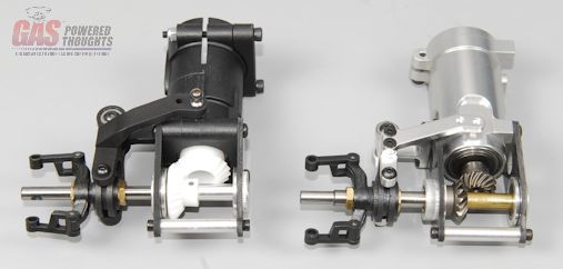 TR Transmissions compared - V2 transmission on right The tail rotor hub is still bored for 5mm, the 6mm t/r shaft is stepped to support this 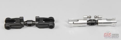 Tail rotor compared - V2 on right Front T/R Transmission Although the transmission housing is the same the T/R drive gears are helical cut metal. So all of the gears in the T/R system are metal 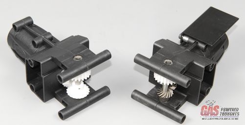 Radikal 30 front trans on left vs V2 on right here you can clearly see the helical cut steel gears used for the front t/r transmission Helical cut metal front t/r drive gears T/R Support Brace This was previously an option for the kit but is now included. Any gas helicopter pilot knows that at various RPM's these suppors can oscillate. This brace reduces or eliminates that 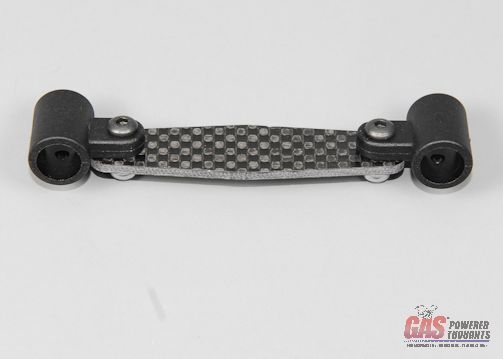 T/R support brace T/R Drive Shaft The original shaft uses a single bearing in its center. The revised version has two bearings spaced as shown. This reduces the amount of any resonance that might develop especially at high rpm 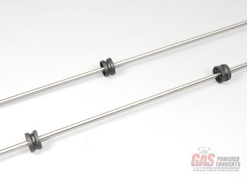 Radikal 30 tube drive - V2 double bearing version on bottom High Performance Clutch The design of the clutch has been modified so that it is now of the leading edge or aggressive approach. This means that as the clutch spins and the shoes extend out, the leading edge engages the liner in the direction of rotation. In the previous design the shoes were cut so the clutch engaged with the leaded edge of the shoe trailing in rotation. the purpose here is for the shoes to better "dig in" to the liner when its locked up. This ensures little to any slip under load. Its still a 59mm diameter, 11mm width clutch which is a pretty signicant size clutch 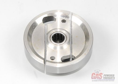 High performance clutch Side Frame halves The rear portion of the side frames have been modified as there are now metal inserts where the mount bolts for the main shaft bearings go. These prevent long term wear around the bolts, allow them to be more firmly tightened and better protects the gear alignments 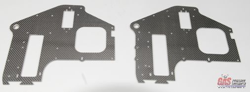 No difference in the size/shape/material of the rear frames - V2 on right here you can clearly see the metal inserts used for the main shaft bearing mounts  Here you can see the metal reinforcements Fan Shroud mount Plate The fan shroud mount plate is now metal to stiffen up the engine mount as this is an integral part of the engine mount mechanism 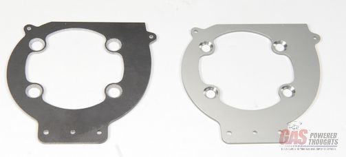 Radikal 30 fan shroud mount - V2 version on the right Video Build Narrative Next Step Getting Started Last edited by carey shurley; 08-19-2021 at 07:46 PM.. |
|
|
|
|
09-14-2012, 05:15 AM
|
#3 (permalink) |
|
Registered Users
Thread Starter
Join Date: Apr 2004
|
Lets get started by taking a look at how the model is packaged.
Everything comes in this cardboard box 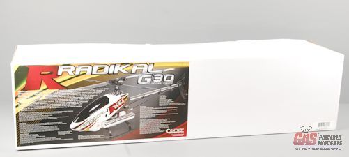 Everything comes in one box Inside there are three different boxes
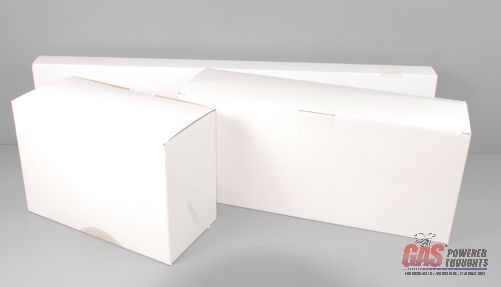 Inside the main box The included manuals are hardcopy printed, and are a combination of drawings and text. You can download the latest versions from the Century site  Included hardcopy manuals the various components are bagged as shown, each section is heat sealed 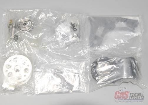 Components bagged separately Next Step Main Shaft Assembly Last edited by carey shurley; 08-19-2021 at 07:47 PM.. |
|
|
|
|
09-14-2012, 05:15 AM
|
#4 (permalink) |
|
Registered Users
Thread Starter
Join Date: Apr 2004
|
I'm going to follow the assembly process found in the manual and the first step there is to assemble the rotorhead/mainshaft components
The Century FBL rotorhead came fully assembled as did the swashplate so there isn't much assembly here 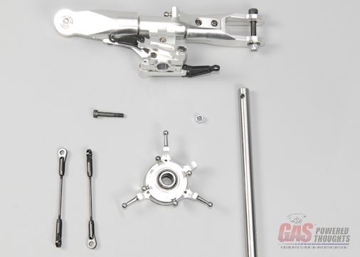 Rotorhead parts The rotorhead slips over the end of the mainshaft where the hole is closest to the end. Then it attaches to the mainshaft using the supplied M4 shouldered bolt and lock nut. You can tighten the two M3 clamp bolts on the outside edge of the rotorhead block and use thread lock here 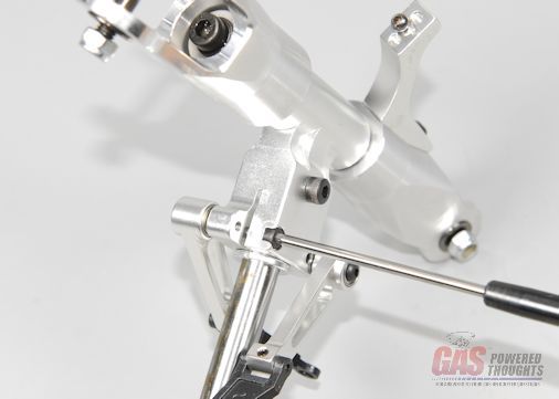 Rotorhead bolted to mainshaft Now slip the mainshaft through the swashplate as shown and clip the swash driver links onto two opposite balls on the inner race of the swashplate. Use the pre-assembled control rods to connect the remaining inner swash race balls to the blade arms as shown NOTE: This kit came with the upper control rods made up for the Flybar head and a separate package that contained the correct rods for the FBL head along with the correct link lengths. So I had to reassemble these. I don't know how the V2 will be final packaged 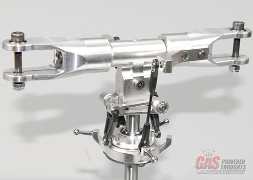 Completed rotorhead assembly Video Build Narrative Next Step Chassis Part 1 Last edited by carey shurley; 08-19-2021 at 07:47 PM.. |
|
|
|
|
09-14-2012, 05:15 AM
|
#5 (permalink) |
|
Registered Users
Thread Starter
Join Date: Apr 2004
|
The first part of the chassis assembly prepares the engine mount to receive the engine and the elevator control arm which must fit between the frame halves. Here are the parts for this step. The package on the right contains the swashplate control parts needed for the FBL rotorhead. As mentioned earlier this kit included this package, I don't know how they will be packaged in the V2 full kit
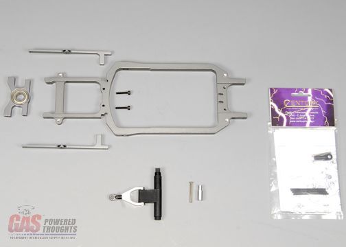 Parts for initial chassis assembly the lower frame supports bolt onto the bottom motor/landing gear frame as shown using M3 bolts. Due to the shapes, these interlock into the lower frame. Don't fully tighten or thread lock these yet 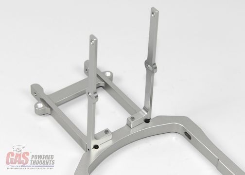 Lower main shaft bearing support This is lower main shaft bearing block, and its shown in the position it will mount. I've bolted it here temporarily so you can see where it goes and how the bearing is positioned (it won't stay there by itself at this point). It will be bolted into place when the left rear frame is installed 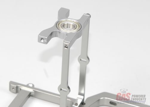 Lower mainshaft bearing positioned the elevator control arm fits between the frame halves so it needs to be completely assembled in advance. Again depending on how the kit is packaged, it may already be completely assembled for the type of head you purchased. In my case it was fully assembled for the flybar head. So the link needed to be replaced with the extended one for the FBL head. 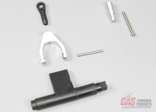 Elevator Control arm parts If you need to install the FBL extension, first push the pin through the control arm so that the A arm can be removed. Then you can remove the ball ink and the bolt that retains it The aluminum extension will push into the end of the A arm where the link was and then the link goes into the end of the extension. The longer bolt supplied with the extension then goes through the A arm, through the extension and threads into the link as shown NOTE: in my case the extension didn't fit well into the end of the A arm so I chucked in a drill and lightly sanded it so that it slipped in without much pressure 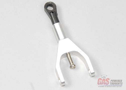 Elevator control arm FBL extension finally reassemble the elevator control arm by pushing the pin back through the bearings and the control arm. I'm going to use some bearing lock where the pin goes through the bearings so that this pin can't vibrate out. This needs to be secured 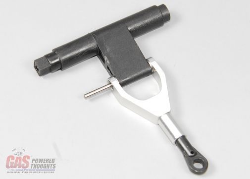 Elevator control arm assembled Video Build Narrative Next Step Motor Assembly Last edited by carey shurley; 08-19-2021 at 07:48 PM.. |
|
|
|
|
09-14-2012, 05:16 AM
|
#6 (permalink) |
|
Registered Users
Thread Starter
Join Date: Apr 2004
|
This is always one of my favorite parts of a build when the motor is prepared for installation. Its time for that now!
Here are all the parts needed to install the motor. As was probably obvious from an earlier step, this build will use an HWC 29 3D Extreme motor. Since I had already put all the components together, I removed the muffler and carb to simplify installation and I remove the pull starter because I only use them if I have no other choice. 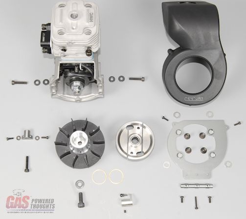 Parts needed to assemble motor the first thing on the motor will be the fan shroud mount plate. Before that can be installed the shroud support spacer needs to be attached to it. This spacer has some flats on it, the mount up against the bottom of the plate as shown 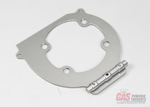 Fan Shroud mount frame support This mounts with M3 button head bolts as shown. These can be thread locked and fully tightened 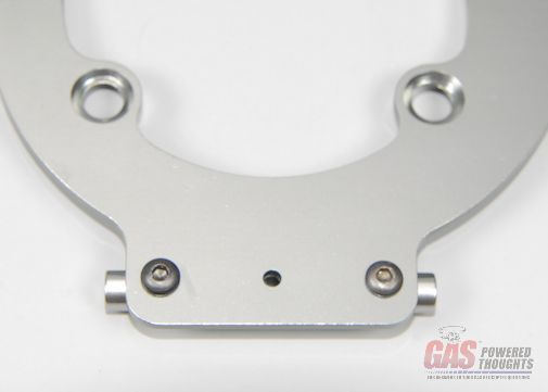 Fan Shroud mount bolts One of the issues with using mass produced industrial motors for precision installations is that sometimes the manufacturing tolerances can interfere with how things fit. These can vary quite a bit in relative terms and it shows up in a couple of places. The first is the clearance between the fan fins and the fan shroud. To address this, the kit includes some small spacers. The only way to be sure if you need these is to install the fan and shroud and see if the fins hit the shroud. If so, you need these spacers. Every one of these I've put together required the spacers so I just put them in. There are four and the simply sit on the four mount lugs on the front of the engne as shown Fan shroud mount spacers Then the fan shroud mount plate bolts on over those spacers using flat head M5 bolts. Install these with thread lock and fully tighten 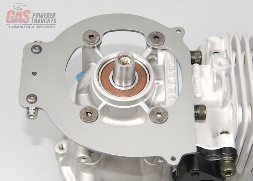 Fan Shroud mount installed The Radikal fan is a double row design, its similar to the stock fan used in the Zenoah RC motor. Its really effective regardless. To help center it on the crankshaft the hub is split and clamps around the crankshaft. You can see the clamp bolt here NOTE: If you are using the HWC 29, Century has a special fan hub for it because the crankshaft is slightly longer than a normal Zenoah motor. If you DON'T use the correct hub you will encounter clearance issues between the clutch shoes and the top inside of the clutch bell 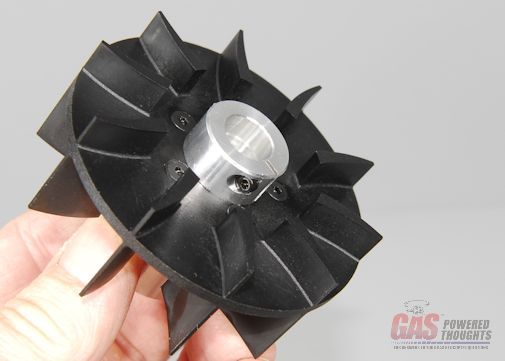 Radikal Fan - bottom clamp So the fan drops onto the end of the crankshaft as shown and bolts into position with an M6 bolt 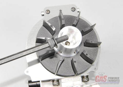 Fan positioned Before you can tighten the fan mount bolt, you'll need to secure the crank so it can't turn. NEVER GRAB THE BACK OF THE CRANK!! The crankshafts are pressed together and its possible to twist them. If you twist one of these cranks you'll just THINK you've seen a gas helicopter vibrate!!! So instead use a piston stop like the one shown. This just threads into where the spark plug would normally go 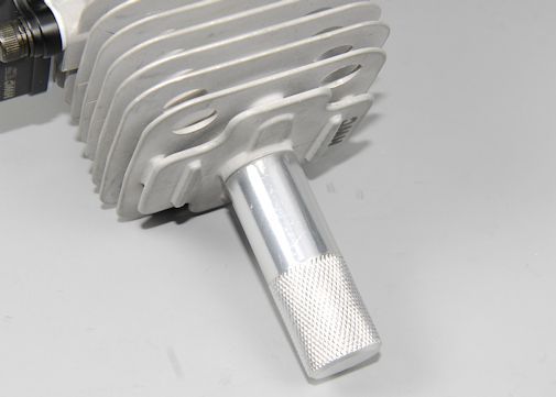 Piston stop installed Now you can crank down on the fan mount bolt. Use thread lock and tighten this well (you don't have to try to kill it though) 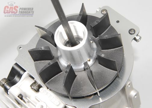 Tighten fan Remove the fan clamp bolt, apply some thread lock and tighten it down firmly. Again you don't have to try to kill it 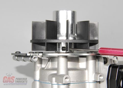 Tighten fan clamp Before mounting the fan shroud I wanted to point out a couple of interesting details. First if you look inside the shroud it has air direction vanes molded in. This is pretty unusual but is one of the reasons this system cools well 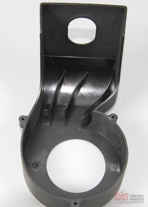 Fan shroud vanes Second, the shroud fits tightly over the cylinder fins which forces all the air to go through the fins, it can't go around them 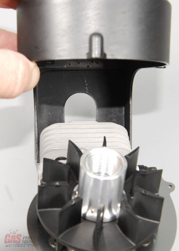 Fan shroud cylinder fit The shroud fits over the fan as shown and against the mount plate. You'll have to remove the piston stop before this can be installed 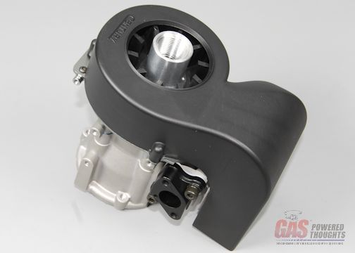 Fan shroud positioned The shroud mounts with M2 socket bolts, there are two shorter bolts and one long one. The long one goes through the rear mount as shown. Just snug these down, don't overtighten them as it will just strip in the plastic 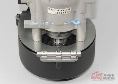 Fan shroud rear bolt The clutch goes on now. It threads into the end of the fan hub. Earlier we were discussing engine tolerances. The other area where this can show up is how deeply the clutch fits into the clutch bell. This is accounted for in the kit by these brass spacers. The complexity here is that you won't know if you need it until the clutch bell is installed Clutch parts Here you can see how these spacers would install, they just slip over the clutch threads. If you are using the HWC 29 and fan hub, you'll likely need one of these to fully engage the clutch Clutch spacers And here you can see how the clutch threads into the fan hub. At this point just snug this down. You may need to temporarily put the piston stop back in for this step 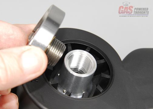 Clutch positioned to install When installed, the clutch will look like this 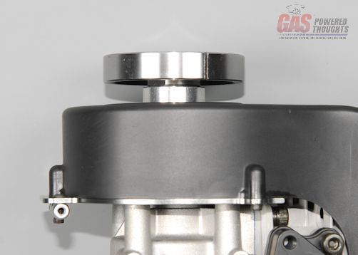 Clutch installed The kit includes a machined control arm, assemble it as shown and use thread lock on the ball 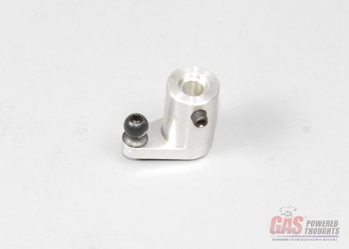 Carb control arm parts Depending on what engine you have, the carb may already have a control arm installed If so remove as shown 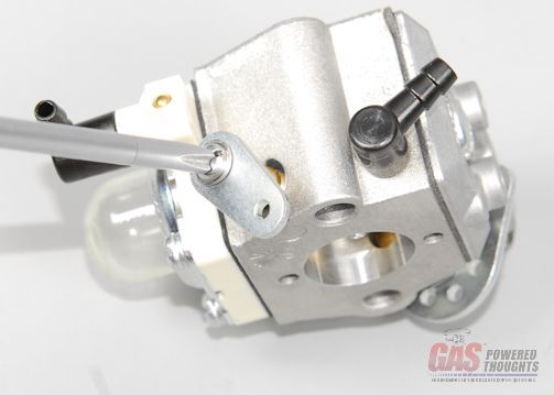 Remove stock carb control arm The supplied carb control arm is sized for the Walbro 643 carb butterfly shaft. This engine uses a larger Walbro 990 so the control arm wont fit over the shaft. I drilled this larger with a #12 drill which fits perfectly. Be careful not to drill all the way through the arm 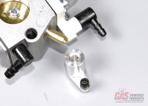 Carb control arm axle fit The arm can be installed on the carb as shown. Put thread lock on the set screw and just lightly tighten it. Now move the throttle back and forth through it complete through and reposition the control arm so that there is an equal throw in both directions. Then you can fully tighten the set screw 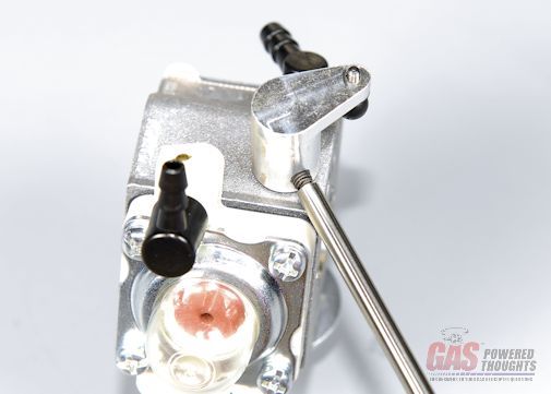 Carb control arm installed The engine is ready to install into the motor/landing gear frame, so you'll need to retrieve that assembly previously built 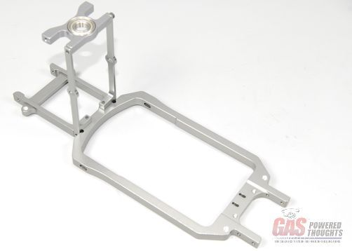 Motor/Landing Gear frame The complete engine slips into the motor frame as shown 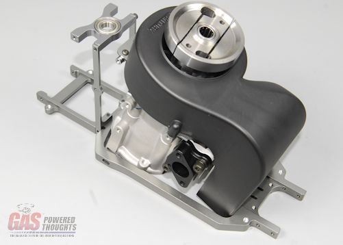 Engine inserted in motor frame Using M4 bolts and washers mount one side of the engine on the rear mount. Note that one washer goes between the frame and the motor and the other is on the outside of the frame 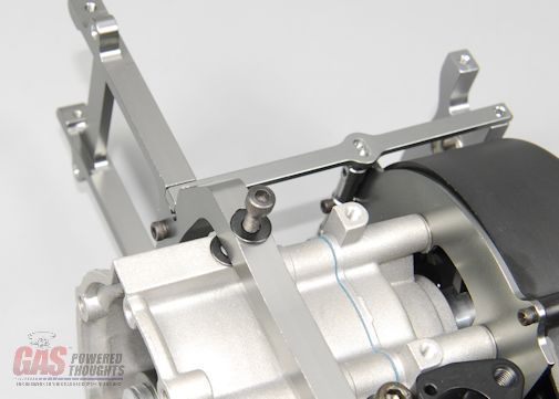 Motor right side mount bolt and repeat that on the other side. Don't use thread lock or fully tighten these 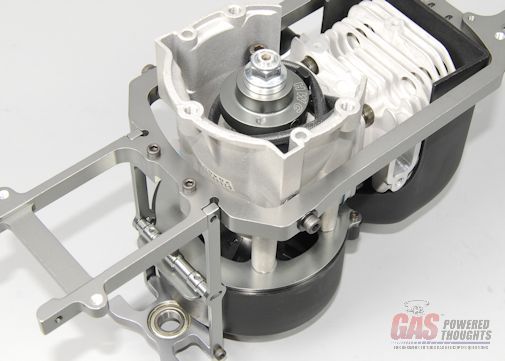 Motor left side mount bolt Using another M4 bolt mount the front motor mount into the top of the cylinder. The std Zenoah PUH motor comes with a tapped hole on the cylinder head. If for any reason you have a non-std motor and it does not, you'll HAVE to drill and tap a hole here because its critical for motor installation/mounting. Push down on the motor so that the mount is flat on the bottom plate. I'd suggest using a high temp RTV on the threads and fully tightening this bolt 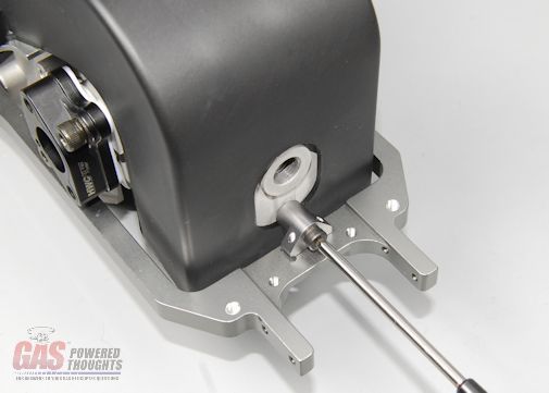 Install front motor mount and using M2 bolts attach the front engine mount to the bottom plate as shown. Don't thread lock or fully tighten these yet 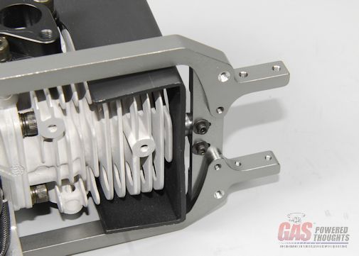 Front motor mount retainer bolts Video Build Narrative Next Step Assemble Left rear chassis/Main Drive Last edited by carey shurley; 08-19-2021 at 07:49 PM.. |
|
|
|
|
09-14-2012, 05:16 AM
|
#7 (permalink) |
|
Registered Users
Thread Starter
Join Date: Apr 2004
|
With the engine ready to go, time to start putting the chassis together. This starts with the left rear plate. Here are the parts needed
 Parts needed to assemble rear chassis Install a M3 x 6 button head bolt as shown in the upper main shaft bearing block using thread lock 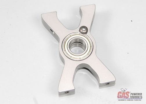 Prepare upper main shaft bearing block Select the left rear chassis plate. The flange on the elevator bearing should be on the inside of the chassis when positioned as shown. Also install the frame brace as shown. If not, use the other plate instead. Use the length of bolts indicated. Don't thread lock or fully tighten any of these yet 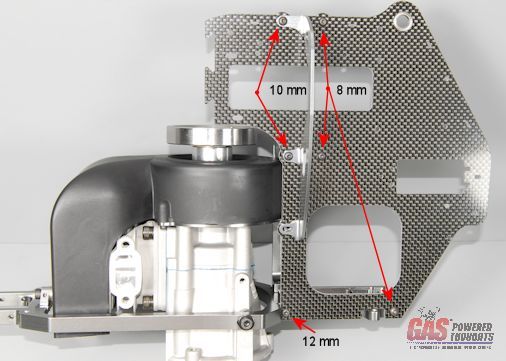 Mount Left rear chassis plate here you can see the position and orientation of the main shaft bearing blocks. The upper block mounts with the protruding bearing on the inside of the chassis. 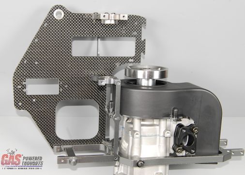 Left rear chassis plate - inside view Standard One Way Bearing Main Drive Here we'll assemble the std one way bearing main drive. This is the standard main drive that comes with the V2 kit. Inside the hub are two rather large stacked one way bearings 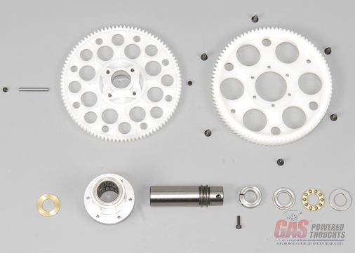 Main Drive Parts - One Way Bearing Start by mounting the main gear to the hub, the gear is directional where one side has a recess. This side installs over the hub as shown. Secure with the flat head bolts using thread lock 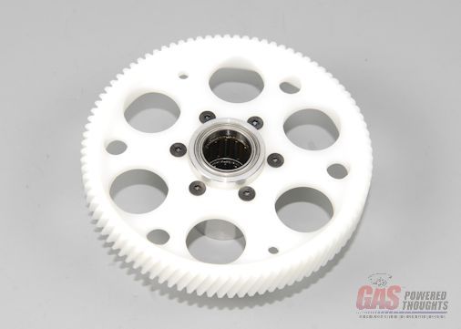 Main gear mounted There are 3 distinct parts that have to properly align to install the TR drive pin/retainer. Because of tolerances, I would suggest that you check to make sure that these parts align properly and the retaining pin can be pushed through the assembly. If not try rotating all the parts differently. If you can't push it through easily you need to adjust the holes in the main shaft or inner bearing race until it will 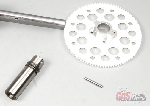 Check pin alignment Apply grease to the lower part of the inner race and twist it into the drive hub as shown until it seats against the upper bearing 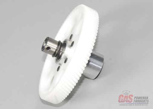 One way inner race inserted The TR upper front drive gear comes with the hub pre-installed. Install a set screw on one side with thread lock, thread it in until it is flush with the outside only 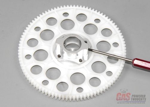 Set screw backing installed The upper TR Drive gear fits over the main drive inner race as shown 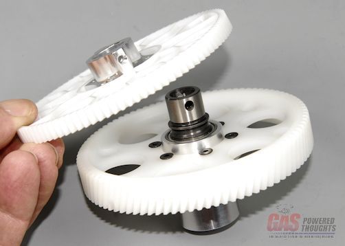 T/R Drive gear positioned and here you can see the completed main drive assembly 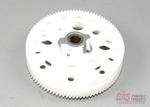 Main drive assembled Now it can be installed in the previously assembled chassis. Position it as shown in the chassis 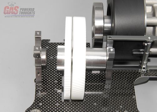 Main drive positioned there are two components that fit above the main drive gear in the stack, a thrust bearing and a collar. The thrust bearing is not directional, it doesn't matter whether the smaller or larger race faces up or down. Just grease the bearing before putting the parts together. The collar will install with the "ridge" facing the thrust bearing Thrust bearing and shaft clamp Select the previously assembled main shaft assembly, start to push it through the upper bearing and insert the thrust bearing/clamp as shown. Push the shaft through them and partially through the main drive hub assembly Main shaft inserted with upper spacers the lower spacer will be inserted in the position shown. Push the main shaft through this spacer and through the lower bearing block. When the shaft is flush with the bottom of the lower bearing block, the pin hole in the shaft will be in about the right position for the next step Lower spacer position Use a screwdriver or bolt driver to align the holes in the 3 parts (hub, inner race, shaft) 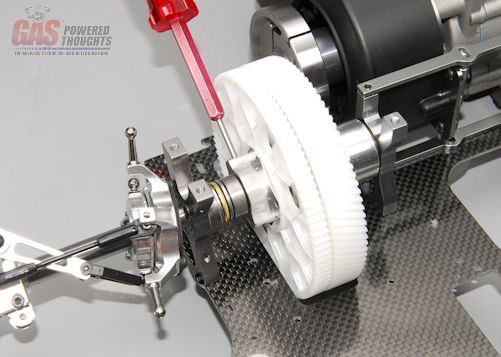 Align TR drive gear retainer pin holes Keeping the parts in place, push the retaining pin through the open side of the TR drive hub. Using a small instrument to push it through the main shaft until it bottoms out against the previously installed set screw in the hub 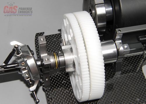 TR Drive pin inserted now insert the remaining set screw to capture the drive pin. Use thread lock. DO NOT OVERTIGHTEN this, its simply not necessary 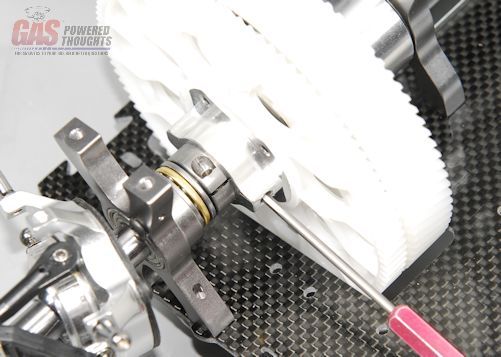 Fix TR drive pin position Insert the 2.5mm bolt into the shaft clamp but don't fully tighten this yet 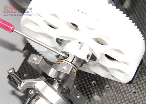 Shaft clamp bolt inserted This completes the installation of the standard one way bearing main drive I'm a big fan of sprag bearings, which are very common in autorotation hubs for helicopters. As such I wanted to show the Century sprag bearing setup As a note to those who are interested in maximum weight savings, the sprag hub weighs 1/2 oz less than the std one way assembly OPTIONAL SPRAG BEARING Main Drive Here are the parts needed to assemble the sprag bearing main drive hub. NOTE - the main gear is different than the one used on the std one way hub and the correct gear is included in the sprag upgrade kit 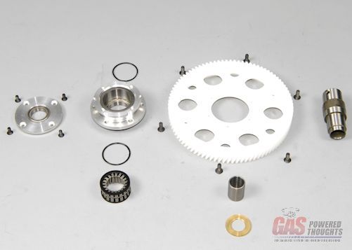 Sprag Bearing parts start by inserting one of the o-ring spacers into the bottom of the sprag drive cavity as shown 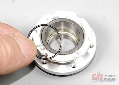 Insert lower o-ring Now its time to insert the actual sprag bearing. Here it is. If you look really close, you'll see the number 422 imprinted on the outer retaining cage. This side of the bearing MUST BE INSERTED DOWN into the cavity. If you get this backward, the bearing will engage backwards and won't drive the rotor head in the correct direction 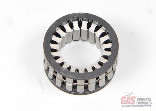 Sprag bearing directional marking after inserting the bearing, another o-ring spacer goes on top of it as shown 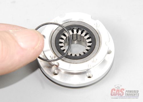 Upper o-ring spacer The sprag bearing cover will be installed as shown using the flat head screws 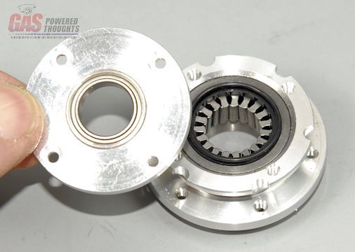 Lower sprag bearing cover here is the view with the bearing cover installed 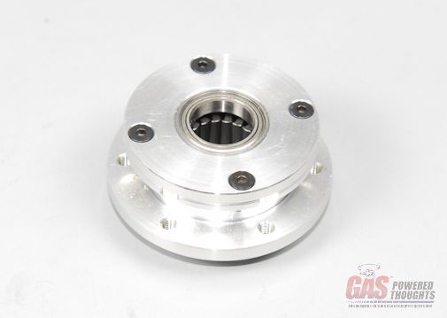 Sprag cover installed flip the assembly over and generously grease the inner bearing 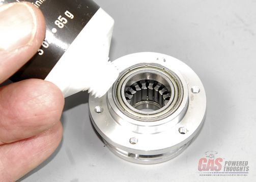 [SIZE="2"]Lube sprag bearing[/SIZE 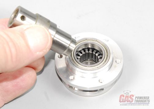 Insert sprag inner race ] the inner race will be installed in this orientation Sprag inner race position/orientation work the inner race into the bearing using a combination of rotation and pressure. These two parts do not assembly easily, you'll have to really work the inner race around in the bearing until you can push it in But once it goes into the bearing, push it in until it seats into the upper and lower bearing as shown 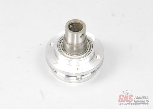 Sprag inner race installed Now you can install the main gear onto the hub as shown using thread lock 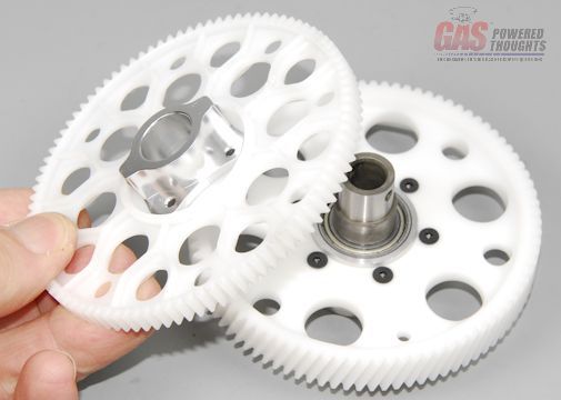 Assemble Sprag main drive the assembly stack to install the sprag bearing assembly into the chassis is almost identical except there is a spacer that fits between the bottom of the sprag hub and the lower copper spacer Here you can see the completed assembly 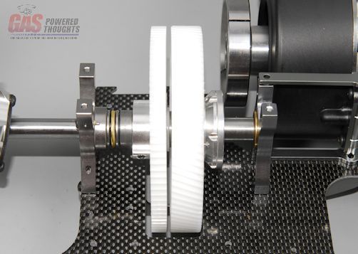 Optional sprag bearing drive installed Video Build Narrative Next Step Fuel tank assembly Last edited by carey shurley; 08-19-2021 at 07:51 PM.. |
|
|
|
|
09-14-2012, 05:16 AM
|
#8 (permalink) |
|
Registered Users
Thread Starter
Join Date: Apr 2004
|
Time to put the fuel tank together. For those of you who have read my various ramblings, you know that I have my own way of doing things. Fuel tanks are one of those things that I have my own plumbing regiment that I always use.
The Century fuel tanks are somewhat unique in how they mount and as a result its difficult to plumb them the way I want to................but I still will. But first, I'll depict how the tank should be built based on the parts that come in the kit Stock Tank Build here are the parts provided in the kit to build the fuel tank. It includes some gasoline proof fuel tubing. Note: make sure you don't use normal glow fuel tubing......it will melt 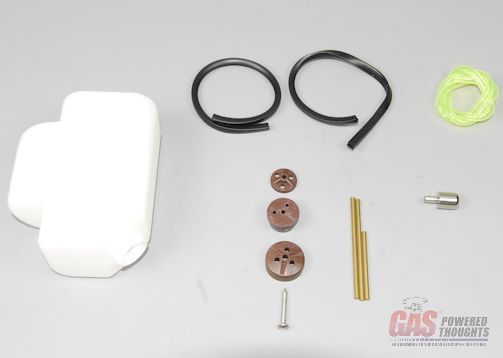 Fuel Tank Parts So you still need to build a vent, a return and a fuel feed. There are 3 pieces of tubing in the kit. Use the short one to build the fuel feed as shown. The tubing is a bit stiff for this purpose but I'll use whats provided. You'll need to bend the other two tubes in a 90 degree angle so that they reach near the top of the tank when installed. If you don't have a tubing bender, you'll need one for this Insert the two bent tubes such that they would be at the top of the triangle formed by the holes in the fuel stopper parts. The fuel feed tube would be inserted in the bottom 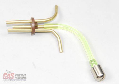 Fuel Tubing Positions now push the stopper over the exposed tubes as shown. This will be easier if you use some sort of lubricant, even soapy water or windex 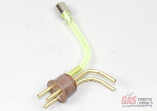 Fuel Tank Stopper with tubing slip the tank cap over the top of the tank stopper and push the provided screw through it as shown 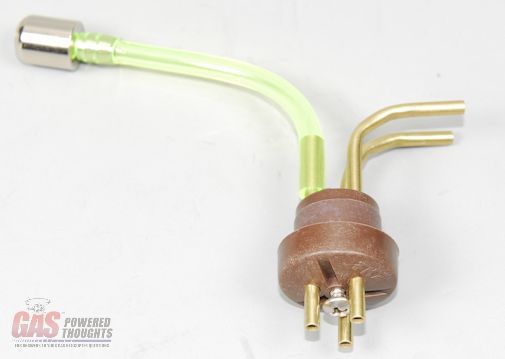 Fuel tank stopper cap positioned Insert the fuel tank stopper into the tank, you'll need to work the tubing parts into the hole. Use a lubricant on the stopper to simplify slipping into the tank 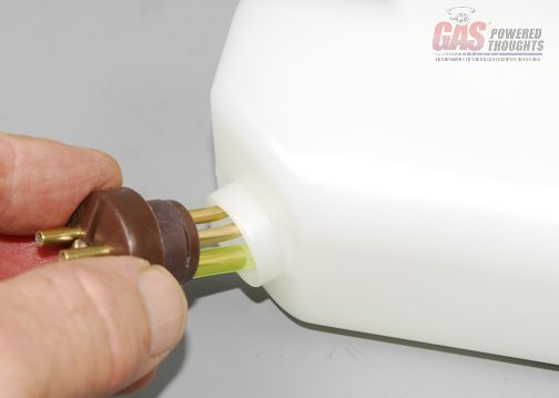 Fuel tank stopper inserted Align the stopper so that the two "vents" are facing up, the ends will be near if not touching the top of the fuel tank. Tighten the screw in the center of the tank until the stopper is tight and can't rotate 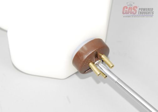 Fuel tank stopper tightened Here's the completed fuel tank using the parts provided in the kit 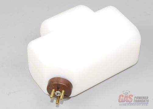 Fuel Tank Completed The fuel tank will push into the rear graphite frame plates. The kit includes rubber channels that cushion the tank and cover the sharp graphite edges on the frame. These are pre-cut to the correct length so simply position it as shown and work it onto the frame 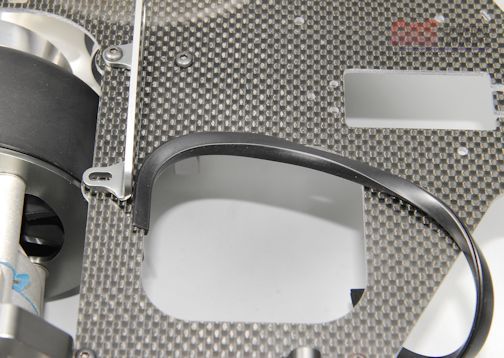 Left Fuel Tank guard position when properly positioned, it will install as shown. If it appears too long, go back and work each corner to make sure the guard is completely seated. 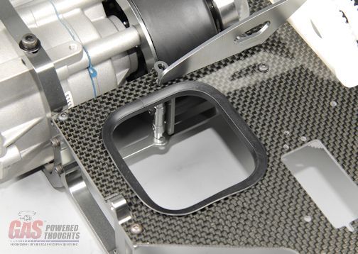 Left fuel tank guard installed the fuel tank simply pushes into the left frame as shown. Push it in until it bottoms on the tank 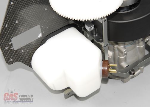 Fuel tank installed - inner view and here's how it looks from the outside of the left rear frame 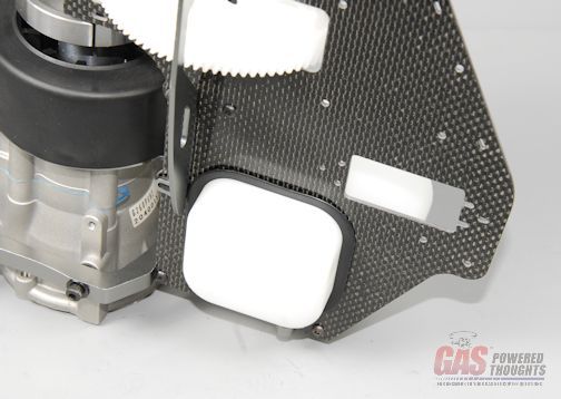 Fuel tank installed - left view okay, using the supplied fuel tank parts thats how you build and install the fuel tank now, I'll show you another optional way to build the tank using "my method" Optional fuel tank assembly I've never been a fan of the plastic tank caps that squeeze together, over time they distort from the pressure and fuel and its easier for the fuel line to slip off of plain brass tubes. So I like to use machined tank fittings and an aluminum tank cap here are the parts use for this setup 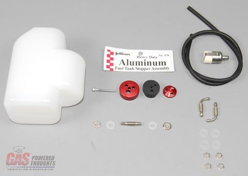 Parts for Optional tank assembly I often use Miniature Aircraft fittings but because of the angle of the tank surface and the need for a 90 degree fitting instead I'm using Tettra fittings like these 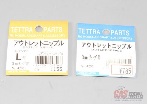 Optional Tank Fittings I'm using viton fuel tubing, its very flexible and normally comes with Zenoah motors. The HWC motors come with a felt clunk like the one shown. I've cut the fuel pickup length to 6" and it slips over the straight fuel fitting. I've prepared the L fittings as shown 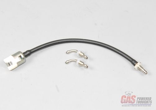 Fuel tank fittings I've marked the tank where I'm going to drill holes for the fittings. The marks are approx 10mm measured from the flat top/bottom of the tank 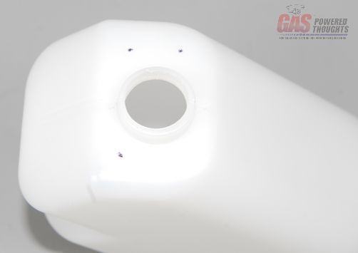 Tank Fitting Position Marks And here I've drilled the holes. They are just slightly smaller than the threads on the fittings for a tight fit 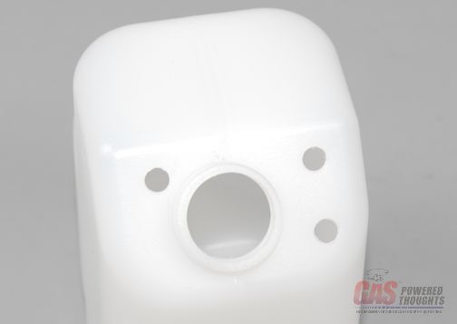 Fuel Fitting holes So using angled pliers I installed the tank fittings for the vents and dropped in the fuel pickup clunk/line and inserted the fuel pickup fitting. The Tettra fittings include teflon sealing washers and the nuts. Small amount of thread lock and tighten them up 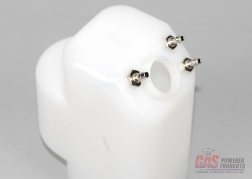 Tank Fittings installed So this is the Sullivan aluminum tank cap. I used the black gasoline proof stopper and put it together without tightening the bolt. You want to line up the stopper holes so that they do not line up with the holes on the aluminum parts making it a sealed stopper. This gets inserted into the tank opening and then tightened up. 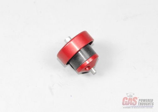 Tank cap assembled And here you can see the fully assembled tank using my optional config 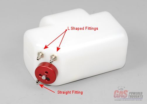 Optional Tank completed Just like the stock tank, it is inserted into the left rear frame as shown  Tank positioned to install And is pushed into the frame until it seats on the protruding center section of the tank 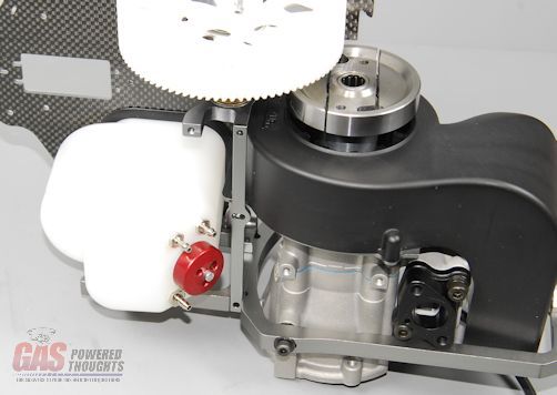 Optional tank installed Video Build Narrative Next Step Chassis Part 2 Last edited by carey shurley; 08-19-2021 at 07:53 PM.. |
|
|
|
|
09-14-2012, 05:16 AM
|
#9 (permalink) |
|
Registered Users
Thread Starter
Join Date: Apr 2004
|
Complete Rear Chassis
At this point the rear part of the chassis can be completed. Here you see the parts needed which includes the previously assembled elevator bellcrank 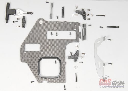 Parts for Rear Chassis completion Start by building the bellcranks, starting with the ail/pitch bellcrank insert one of the bearings 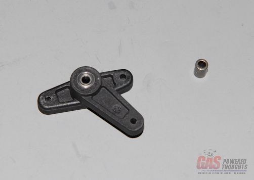 Insert first bearing in side bellcrank then flip it over and drop in the bearing spacer Center spacer in side bellcrank finally push in a remaining bearing. Install link balls as shown, use slow CA adhesive in the plastic bellcrank. 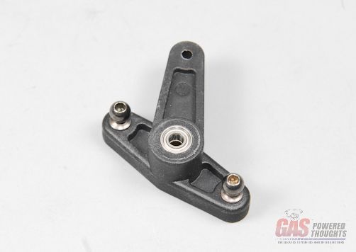 Second bearing and balls for side bellcrank complete the remaining ail/pitch bellcrank and install the remaining link ball on each. Also build the elevator bellcrank by installing link balls as shown 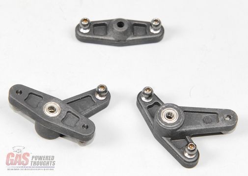 Complete bellcranks Now take the previously assembled left frame/motor assembly and install the left rear canopy mount as shown using an 8mm bolt with thread loc 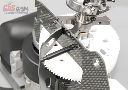 Install rear canopy mount on left frame With the right rear frame, also install the rear canopy mount with an 8mm bolt and thread lock mount two of the frame spacers as shown using 8mm bolts but dont thread lock or tighten yet also push the elevator bellcrank into the rear upper bearing as shown, the square end will protrude through to the right outside of the frame as shown if you haven't already installed the rubber tank damper in the frame half, do so now 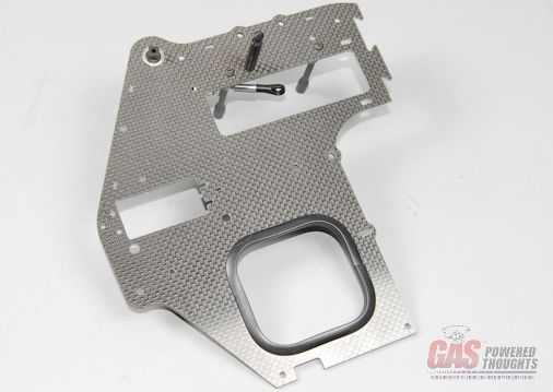 Install canopy mount and spacers on right frame Here's an inside view so you can see the parts positions 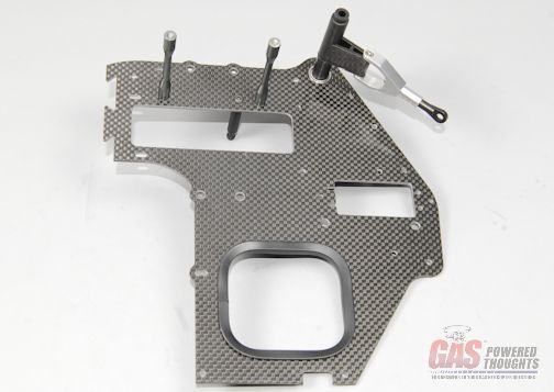 Right Frame parts installed The right frame is going to be assembled to the existing chassis and will be positoned as shown. In order for it to easily slip into place, start by slipping the front of the tank cutout over the fuel tank cap/fittings. You can push it over the tank after that has been cleared 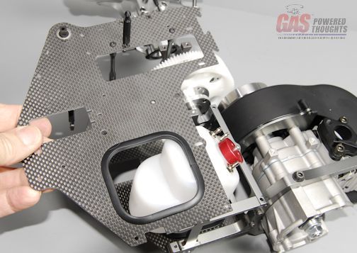 Right Frame position assemble the right frame using these length bolts. As with the left rear frame, the frame brace will be installed as shown. Don't tighten or use thead lock yet 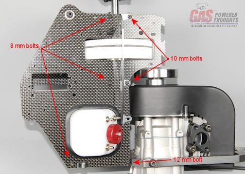 Right Frame bolts you'll need two 8mm bolts to complete the frame attachment by connecting the frame spacers to the left frame as shown 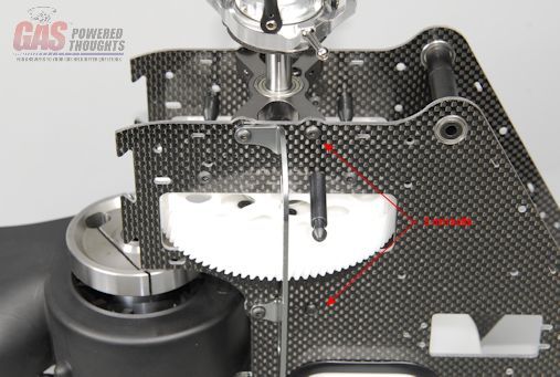 Left frame bolts The Ail/Pitch bellcranks can be installed now. You'll need a frame spacer, the two bellcranks, the two spacers (positioned as shown) and two 25mm bolts 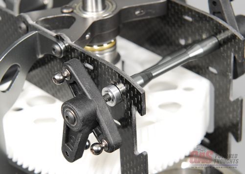 Install Front bellcranks Install Front bellcrankswhen complete the bellcranks will be oriented as shown 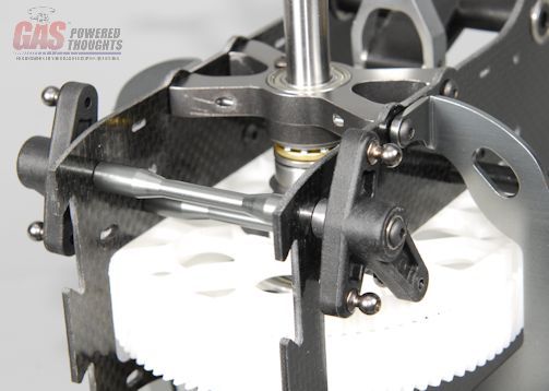 Front bellcranks installed the previously assembled elevator bellcrank will slip over the elevator control arm at the rear of the frame. It will be positioned at a slight downward angle as shown 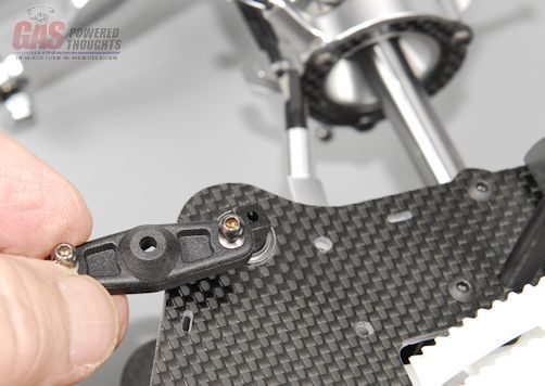 Elevator bellcrank position The elevator bellcrank is installed with a 12mm bolt using slow CA as it threads into the plastic axle 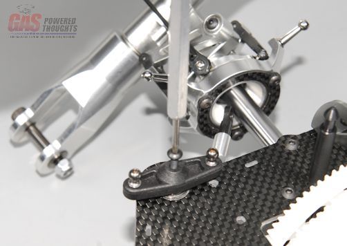 Elevator bellcrank installed connect the elevator bellcrank to the swashplate and you can see another view of the completed control bellcranks 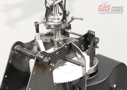 Completed bellcranks Completed bellcranksThe rear part of the chassis is now complete. Up to this point, none of the bolts have been tightened or thread locked. Go back and start to tighten all of the chassis bolts using thread lock. This will ensure good alignment of the frames/main shaft/bearings. NOTE: you will also need to tighten the clamp bolt on the main shaft retainer. Push down on the main shaft and lift up on the retainer so that it pushes against the thrust bearing. Tighten the clamp bolt using thread lock This completes the rear part of the central chassis 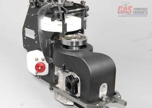 Completed rear chassis assembly Install Clutch Block Next will be the clutch bell and bearing block. Here you can see the parts needed Century offers multiple gear ratios for most of its gas powered models, the Radikal 30 V2 is no different. The stock kit comes with a 14 tooth pinion. Because I like to run higher engine RPMs I'm going to install an optional 13 tooth pinion. Regardless the assembly process will be identical 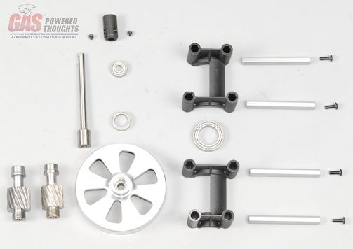 Clutch block parts slip the large lower clutch bearing over the clutch bell as shown 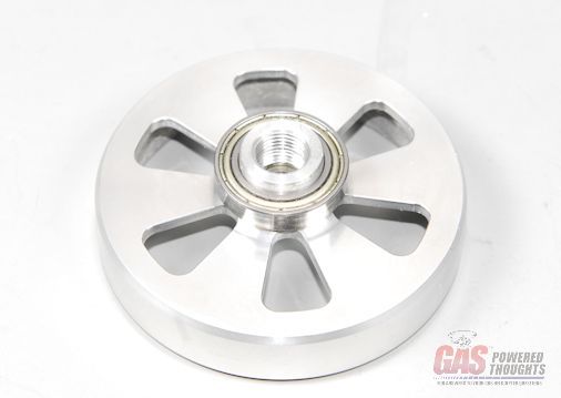 Install lower clutch bearing Select the pinion gear and thread it into the clutch bell using thread lock. Tighten firmly 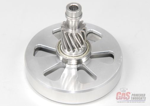 Install clutch pinion install the upper pinion bearing by slipping it over the end of the pinion as shown  Install pinion upper bearing Select one half of the clutch bearing block and push it over the bearings as shown 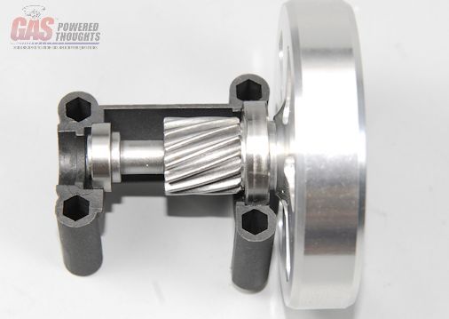 Install clutch block half Now take the other half and push it over the other side. Push the four frame spacers through the bearing block case as shown and press the upper start shaft bearing into place as also shown 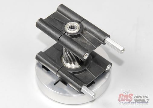 Complete clutch block Turn the clutch over and slide the start shaft through the clutch bearings as shown until it seats on the inside bearing in the clutch 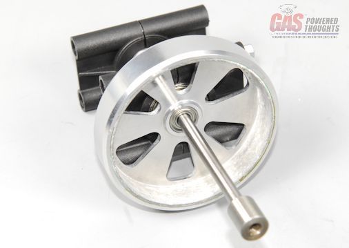 Insert start shaft turn the assembly over and locate the flat on the start shaft. Install the start coupler over the shaft such that one of the two threaded holes align with the flat on the shaft 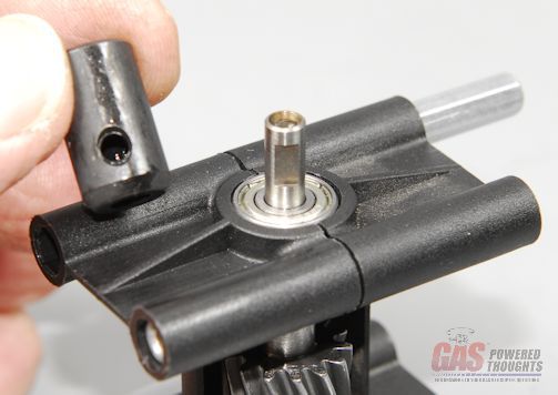 Start coupler positioned install two set screws as shown with thread lock. Install the first one against the shaft flat and then install the remaining one 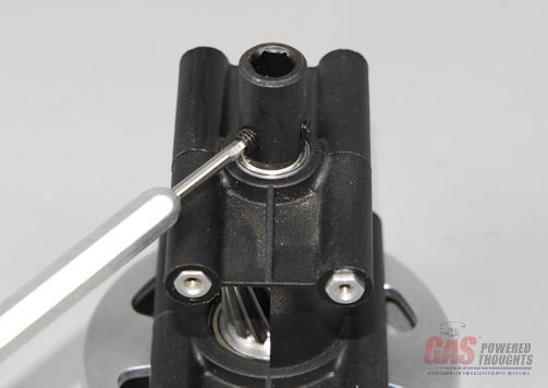 Install start coupler Now that the clutch block is finished it can be installed on the chassis Here is where there is some fun. The assembly instructions completely skip this step. Its not shown at all. I was a bit curious about how this might be installed given the position of the main gear and the motor and I quickly found out it CAN'T be installed with everything in place, the bell won't fit between the main gear and the clutch itself So the easy way to do this is to remove the three 5 mm bolts that hold the engine in place and let it drop slightly in the frame. If you have installed the carb/muffler/isolator block, they'll all have to be removed 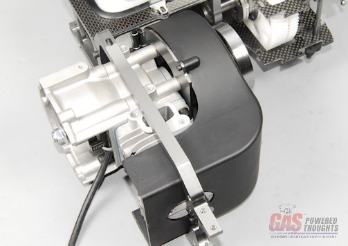 Loosen and lower motor once the motor is lowered, the clutch bell will easily slip over the clutch and into positon 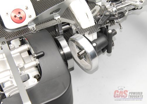 Position clutch block It bolts into position with four 8mm bolts as shown. Don't use thread lock or tighten these now 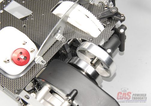 Install clutch block The engine can now be pushed back up into the frame such that the clutch engages into the clutch bell/start shaft. Reinstall the 5mm bolts that hold the engine but don't tighten yet. You might remember back when the engine was assembled I mentioned there were some small brass spacers that could be installed under the clutch The clutch shoes should be flush with the bottom of the clutch bell. If at this point, you see the clutch shoes protruding out from under the clutch bell, you'll want to drop the motor, spin the clutch off and add one or both of those spacers and then reinstall the clutch/motor. Clutch spacing Once the engine is bolted back into place, the clutch block installation is completed for now 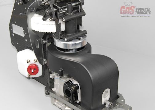 Clutch block installed Clutch block installedVideo Build Narrative Next Step assemble radio frame/tray Last edited by carey shurley; 08-19-2021 at 07:55 PM.. |
|
|
|
|
09-14-2012, 05:17 AM
|
#10 (permalink) |
|
Registered Users
Thread Starter
Join Date: Apr 2004
|
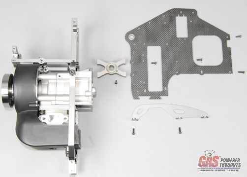
This step will assemble and install the front radio tray/frame components. There are two trays, one longer one usually for the battery and a shorter one, usually for the gyro. Here you can see all the parts needed
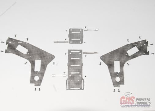 Radio Tray/Frame Parts First attach the four frame spacers to the two trays. The mount holes in the trays are beveled on one side, insert the 2mm flat head bolts from this side 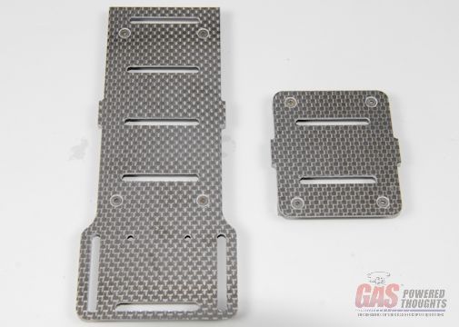 Trays - Top View they will thread into the frame spacers positioned as shown. There are "flats" on these spacers, they will fit against the graphite parts. Use thread lock and fully tighten as these parts are in their final position 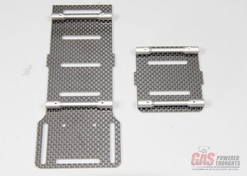 Trays - Bottom View The trays use a tab and slot positioning system, the trays have tabs on them and the frames have slots cut for them. The smaller tray fits into the tab towards the top of the frame, and is symmetrical so doesn't matter which way is forward. The longer tray fits into the lower tab with the larger square end facing forward. Push the tabs into one of the frame sides in the positions shown. The tabs may fit so tightly into the slots that you may need to slightly file the slots. 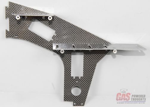 Trays Inserted Use 8mm bolts to attach the frame spacers through the outside of the side frame as shown 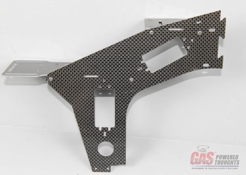 Tray Bolts The other frame half will be installed as shown, again the tabs will interlock with the slots 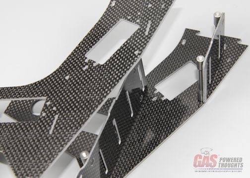 Install other frame half and use 8mm bolts on this side as well. These can be installed and tightened with thread lock 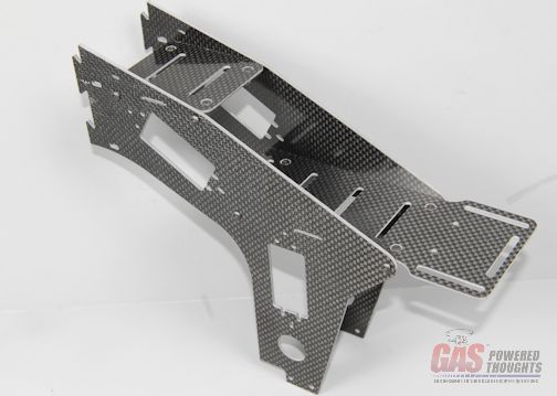 Bolt positions Don't install the two rear bolts into the upper tray frame supports just yet. Shortly you'll need to "spread" this part of the frame open to install it 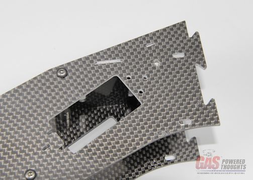 Leave back upper tray bolt out for now Now select the existing rear chassis assembly and you're going to install the radio tray/frame over the front of it as shown 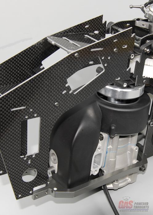 Tray positioned for install To install this, you need to do a couple of things. Lightly "spread" the top rear radio tray frames so that the fit over the outside of the rear chassis frames and position the lower front edges of the radio tray over the end of the landing gear/motor frame. The triangular tabs/slots on the frame pieces can easily be interlocked and pushed together 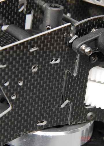 Spread frames and interlock tabs Install 8mm bolts into the clutch block on one side frame as well as the remaining 8mm bolt into the rear mount of the top frame. Use thread lock on all of these 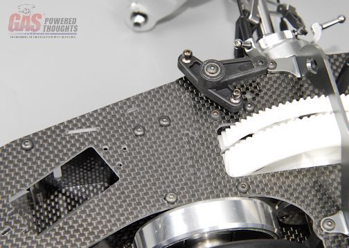 Install left side bolts repeat the process on the other radio tray/frame side bolts 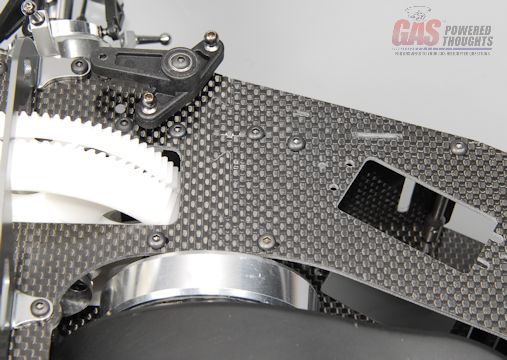 Install right side bolts Mount the radio tray/frame to the lower part of the motor/landing gear frame using four 8mm bolts as shown. Use thread lock and fully tighten 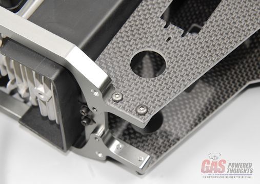 Install lower bolts Here you can see the completed radio tray/front frame assembly in place 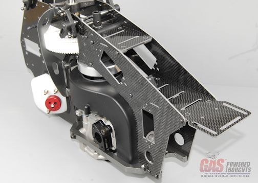 Radio tray complete/installed Video Build Narrative Next Step Assemble/Install Landing Gear Last edited by carey shurley; 08-19-2021 at 07:56 PM.. |
|
|
|
|
09-14-2012, 05:17 AM
|
#11 (permalink) |
|
Registered Users
Thread Starter
Join Date: Apr 2004
|
In this step the landing gear will be assembled and installed on the existing chassis
here you can see the parts needed 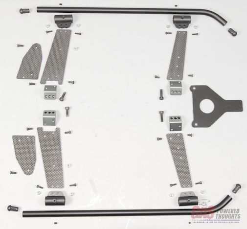 Landing Gear Parts start by putting the plastic skid mounts together. Press the M2 locknuts into cavities on the inside of the mounts and initially install the M2 set screws in the outer skid stops (don't thread these in more than 1-2 threads) 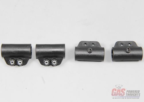 Assemble Skid mounts the rear struts are made up of two graphite parts. The inner strut stiffners attach to the struts using an M3 x 8mm bolt and lock nut. These parts are direction sensitive so look closely at the photos to get them correct 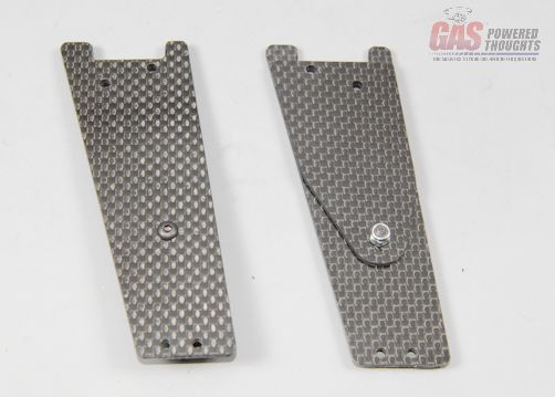 Assemble rear struts Install the skid mount onto the bottom of the struts using M2 bolts that thread into the previously installed lock nuts. The orientation of these is as shown, they are direction sensitive. These can be fully tightened 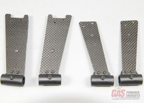 Install skid mounts Install the aluminum strut mounts at the top of each strut. Note each orientation and the bolt lengths shown here. Use thread lock and fully tighten 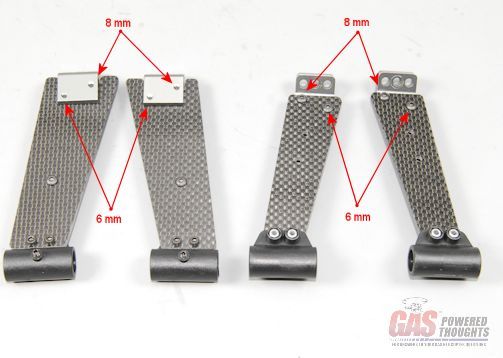 Install Strut mounts Now the rear struts (with the doublers) can be installed as shown on the bottom rear of the landing gear/motor frame. Use the shorter M4 bolts. Don't fully tighten or thread lock yet. 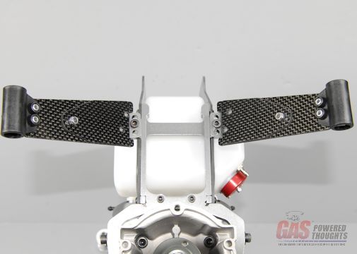 Install rear struts the front strut installation includes the canopy mount plate. Its installed oriented as shown 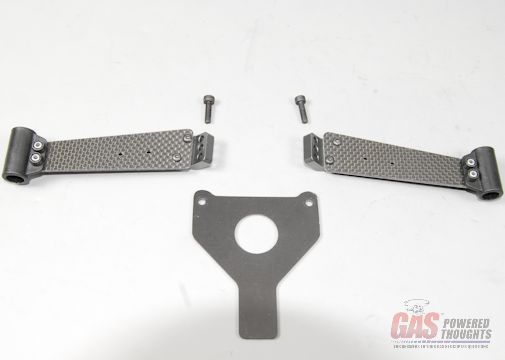 Front Strut Parts install the front struts and canopy mount using the longer M4 bolts. Again dont' fully tighten or thread lock yet 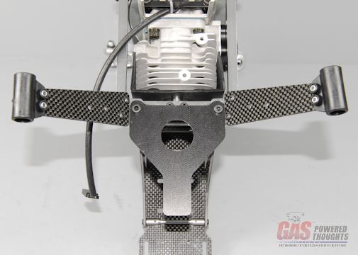 Install front struts/canopy mount Select the two landing gear struts and the four plastic end plugs. Push the plugs into the end of the skids using slow CA. You may have to exert pressure to push these in 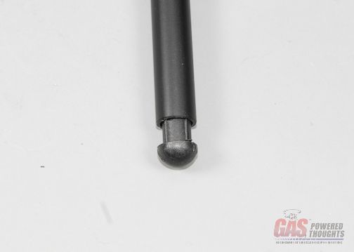 Install skid plugs Now slide the skids into the strut mounts as shown. These fit tightly, you'll need to hold each strut as you push it through. You and use a lubricant if it helps 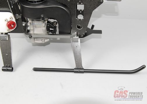 Install skids the correct position of each skid is to have about 1-1/2" extending from the rear of the rear strut as shown 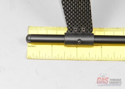 Set Skid position Now tighten up the four set screws to fix the positions of the landing gear skids. You can use slow CA on these go back and thread lock and fully tighten each of the 4mm bolts that attach the landing gear struts to the lower frame. 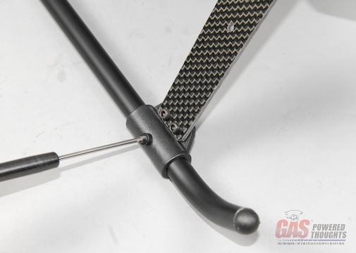 Fix skid positions here's the completed landing gear in position 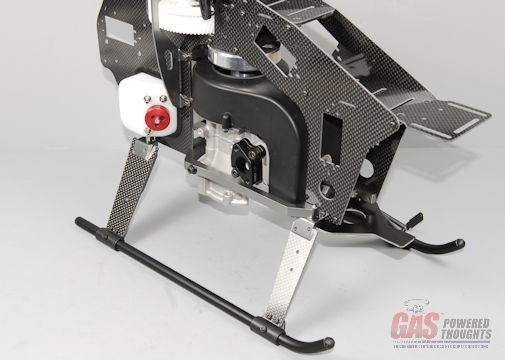 Landing Gear complete There is a step missing from the assembly manual and it has to do with installing the lower bolt on the side frame braces that thread into rear fan mount spacer/engine mount. The kit has two 12mm bolts that go here. Apply thread lock and install as shown 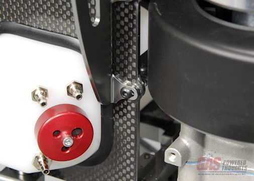 Install missing bolt Video Build Narrative Next Step Assemble Tail boom Last edited by carey shurley; 08-19-2021 at 07:57 PM.. |
|
|
|
|
09-14-2012, 05:19 AM
|
#12 (permalink) |
|
Registered Users
Thread Starter
Join Date: Apr 2004
|
This step will build the tail boom assembly and install it
here are the parts needed to install and assemble the tail boom (some of the parts are longer than you see in the photo) 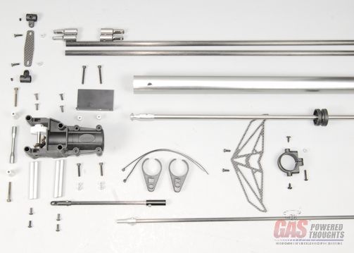 Tail Boom Parts start by pushing the tube drive into the tail boom. Both tubes are symmetrical so it doesn't matter which end is started into the boom. The rubber bearing holders fit tightly into the tail boom so you can't just push them in, you'll need a lubricant 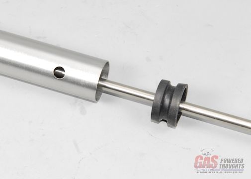 Insert tube drive into boom - use lubricant this is what I use, its silicone based so it doesn't damage the rubber. Lube the two bearing holders as well as the inside of the boom. You'll need to work each of the rubber parts in very carefully and then push the entire tube into place  Suitable lubricant Continue pushing the tube drive in until both ends protrude from the ends of the tail boom equally. That distance will be approximately as shown 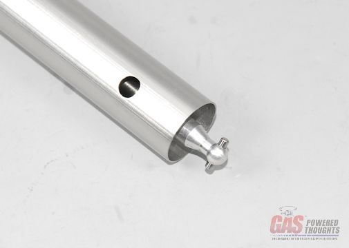 Insert drive - equal distance each end Prepare the front tail rotor transmission as shown, in my kit this was fully assembled I just needed to split the case into two pieces as shown 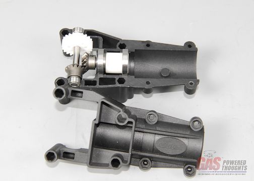 Front T/R transmission prepared for tail boom either end of the tail boom can be used, engage the end of the tube drive into the plastic drive cog on the transmission and then position the tail boom so that its end is against the shoulder in the housing and the holes in the boom align with the tabs molded into the transmission case. The tabs will fix the position of the boom so it can't turn or pull out 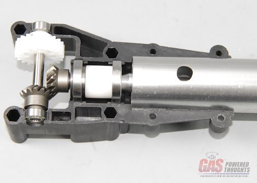 Drive Inserted - Boom aligned Reinstall the other transmission case as shown and push the four metal spacers through the mount holes as shown 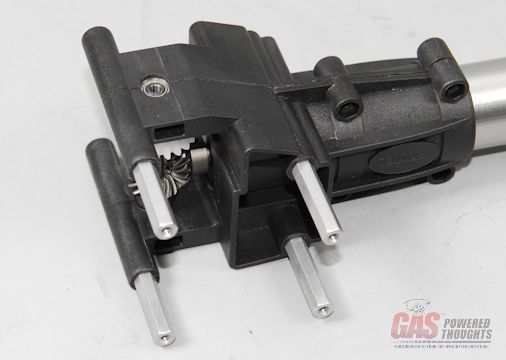 Front T/R Transmission - assembling Push the two aluminum spacers into the top of the boom clamp and then install two M3 bolts through the bottom clamp holes 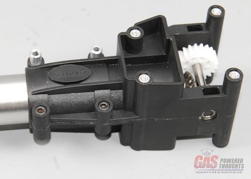 Front T/R Transmission - bolts/spacers inserted Install the gyro plate using the long M3 bolts through the aluminum spacers and through the transmission housing 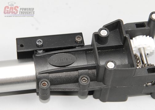 Gyro plate positioned Install M3 locknuts on the left side of the clamp housing as shown and tighten the four bolts 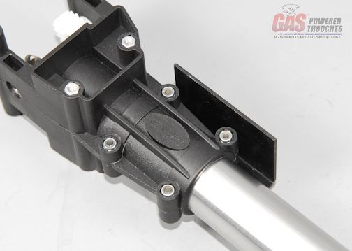 Front T/R transmission - clamped the t/r pushrod supports slip over the end of the long portion of the T/R pushrod 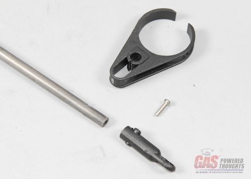 Prepare T/R Pushrod Both supports should be installed and the ball link slips over the end of the pushrod and is held in place by an M2 bolt as shown 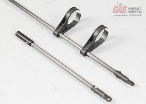 T/R Pushrod supports installed Thread the two parts of the t/r pushrod together. The exact amount to thread the parts together will be determined when the servos are installed 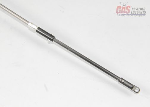 Assemble T/R pushrod Slip the two t/r pushrod supports over the end of the tail boom as shown 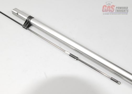 T/R Pushrod installed now slip the t/r boom support clamp over the end of the tail boom. It will be positioned shortly 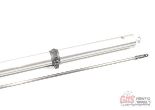 Boom support clamp positioned Now you can install the tail boom assembly into the existing chassis. It will be installed as shown 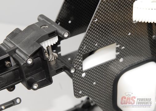 Tail Boom positioned Once the boom is positioned, bolt it into place using eight M3 bolts. These can be installed using thread lock and fully tightened. Here you can see the four bolts on the right side  Tail Boom installed - right and the four bolts on the left side 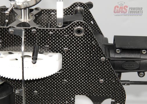 Tail Boom installed - left Now the boom supports will be built. The boom support brace mounts must be slipped over the support tubes first, they will be installed later. The aluminum ends must be glued onto the tubes using an adhesive such as epoxy or JB Weld. The ends are installed such that they will all be parallel to each other on each end. Let these setup before installing 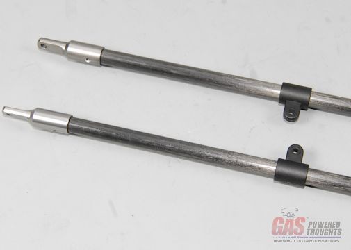 Prepare boom supports The remaining frame support will be positioned as shown below the tail boom Position T/R boom support spacer Use the completed tail boom supports and bolt them onto the frame using M3 x 25mm bolts. The bolts go through the boom supports then through the triangular spacers and then thread into the frame spacer as shown. Don't tighten these yet 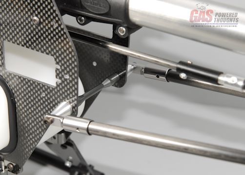 Install T/R boom supports - Front Now reposition the rear boom support clamp as shown, so that it aligns with the ends of the boom supports 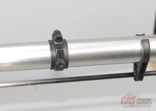 Reposition rear T/R boom support clamp The rear boom support ends are attached to the rear boom support clamp as shown 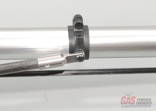 Install left T/R boom support use slow CA and fully tightent these. Now you can go back and fully tighten the front boom support bolts using thread lock 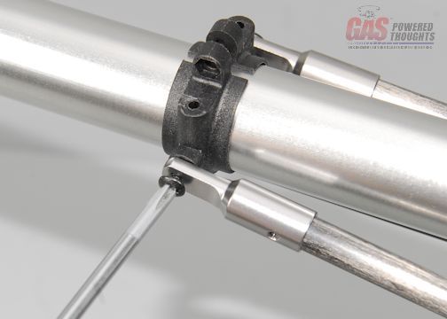 Install right T/R boom support Using the supplied M3 bolt and locknut, lightly tighten the boom support clamp. Looking down the tail boom, the clamp should be parallel with the landing gear 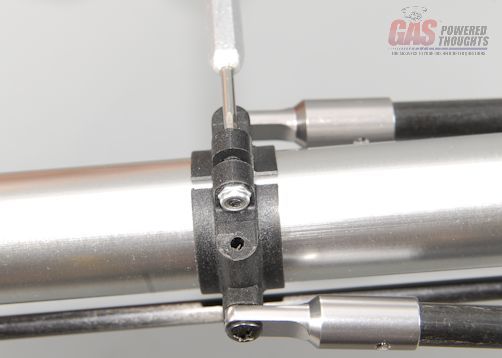 Tighten boom support clamp Install the horizontal fin using 8mm long bolts and slow CA. After this is installed, make sure that the fin is horizontal to the ground. if not reposition as necessary and then fully tighten the boom support clamp bolt to fix its position 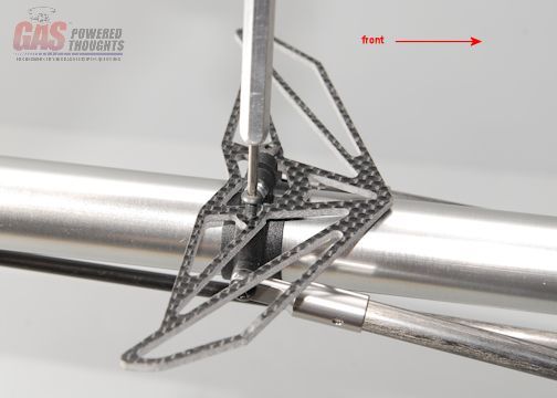 Install horizontal fin Now install the support brace between the boom support brace mounts previously slipped over the boom supports. This requires 8mm M3 bolts and locknuts as shown 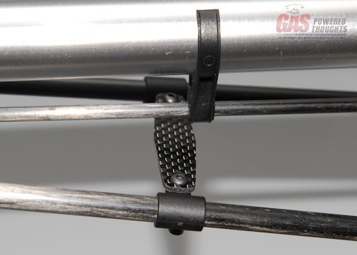 Install T/R boom support brace plate position the boom support brace approximately in the center of the boom supports and then tighten the two set screws as shown which will fix the position of the brace on the boom supports 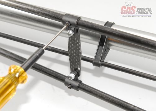 Fix T/R boom support brace position Video Build Narrative Next Step Assemble/Install Tail Rotor Last edited by carey shurley; 08-19-2021 at 07:58 PM.. |
|
|
|
|
09-14-2012, 05:19 AM
|
#13 (permalink) |
|
Registered Users
Thread Starter
Join Date: Apr 2004
|
This step will assemble and install the tail rotor, which will complete the basic airframe assembly for the Radikal.
The last step assembled the entire tail boom except for the rear transmission so it will be completed here these are the parts required to complete the tail rotor  Tail Rotor Parts the kit includes a set of standard 95mm century plastic tail rotor blades. In this build I am using a set of optional Rotor Tech 105mm graphite tail rotor blades. The optional graphite blades are shown on the right 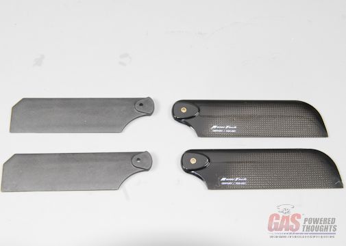 Tail Rotor Blades - Stock vs. Optional the tail rotor hub came preassembled so just need to install the tail rotor blades. The blade and two each of the 1mm spacers are needed for each blade. It will be installed into the t/r blade holder using these shouldered M3 bolts 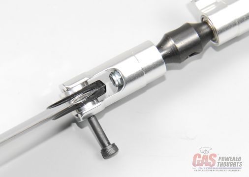 T/R blade mount bolt and the blade installation is completed by using an M3 locknut. These blades should be fairly tight 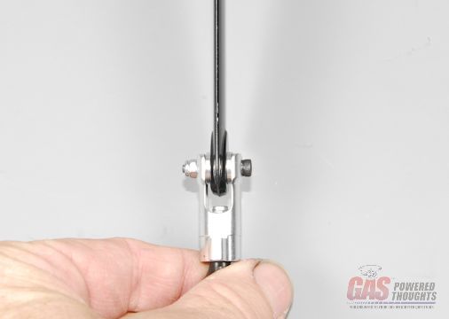 T/R blade mounted Here you can see the optional t/r blades installed in the correct orientation for the blade holders 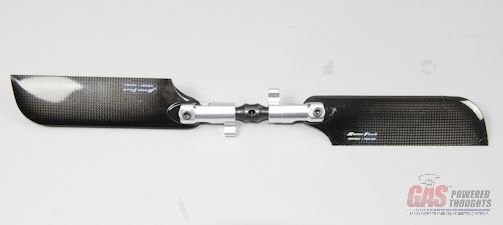 Optional T/R blades mounted because of the very high speed that the t/r turns, its important to balance them. The easiest way to do this is with a balancer such as this Dubro balancer. when properly balanced, the t/r will sit level on the balancer. If not, you need to weight the side that is higher on the balancer. Usually adding a small washer under the locknut is adequate to balance the light blade, however the process of balancing rotor blades is outside the scope of this build thread 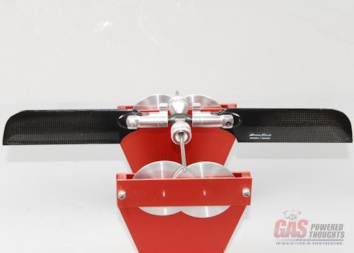 T/R blades balanced the t/r transmission in this kit came preassembled except for a couple of parts Install the control ball on the outside hole in the t/r control bellcrank using thread lock as shown. It must face away from the t/r transmission for proper clearance 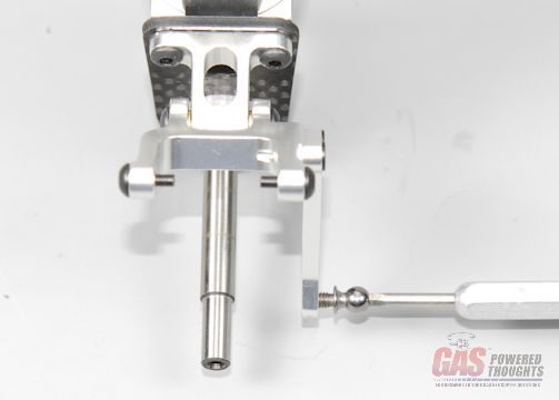 Install rear T/R control ball slide the preassembled pitch control mechanism over the t/r shaft while the t/r bellcrank is as far towards the outer end of the t/r shaft as you can. As you push the pitch change mechanism over the shaft, engage the pins on the bellcranks mechanism into the slots on the pitch change disk. As you continue to push the pitch change mechanism over the shaft continue to move the bellcrank towards the transmission so that it is fully engaged 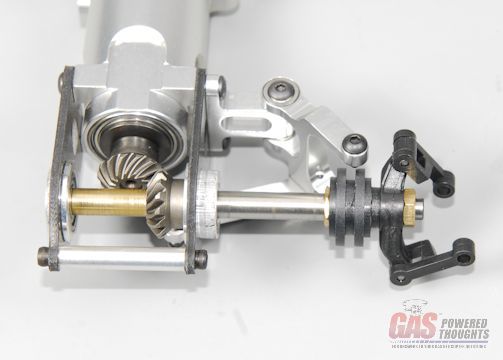 Engage T/R pitch control mechanism here you can see the pitch change mechanism fully positioned 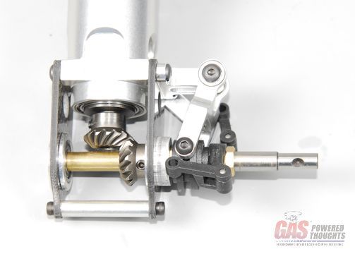 T/R pitch control plate installed now take the previously assembled and balanced tail rotor and get ready to install it on the t/r output shaft. You want to align the threaded hole in the t/r hub with the indentation on the t/r shaft as shown 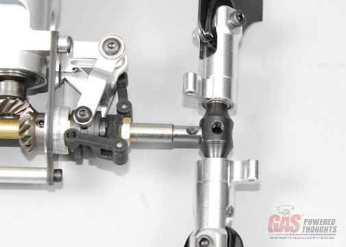 T/R position install the t/r hub over the shaft and thread in the m4 set screw using thread lock so that it seats into the shaft dimple. you may have to slightly rock the t/r back and forth very slightly. fully tighten this set screw 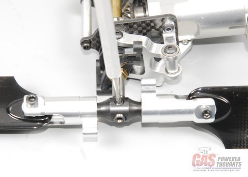 [I]T/R installed/I] now you want to connect the t/r pitch change plate arms to the t/r blade arms. This is done using these small shouldered screws. They will to through the two pitch change arms and thread into the t/r blade arm. Use thread lock and tighten fully 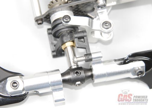 T/R Pitch plate shouldered bolt here you can see both bolts installed in the proper orientation 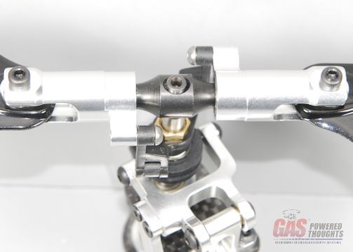 T/R pitch plate installed now take the entire t/r transmission assembly and install it over the previously assembled tail boom. The tail rotor will be on the right side of the model T/R transmission position On the left side of the tail boom you'll see that there is a hole in the t/r transmission as well as the tail boom itself. You want to turn the transmission until these holes align as shown 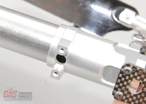 T/R transmission retaining hole the kit includes a plastic t/r retaining plug as shown 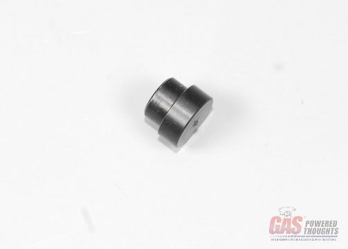 T/R retaining plug push this plug into the previously aligned t/r transmission/boom hole until it seats. This will be held in place by the vertical fin 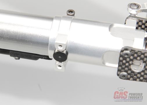 T/R retaining plug installed the vertical fin will install as shown 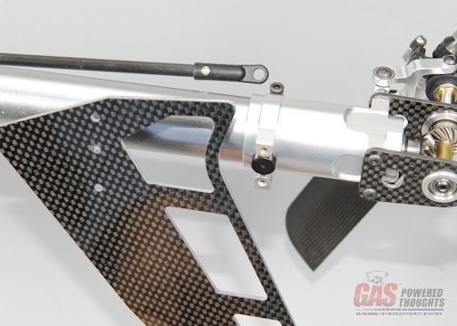 Vertical fin position install the vertical fin as shown using 8mm m3 bolts. Use thread lock and fully tighten 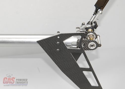 Vertical fin installed now tighten the clamp on the right side of the t/r transmission using an M3 bolt and thread lock Tighten T/R clamp bolt look underneath the tail boom and push the t/r control ball link over the control ball on the t/r bellcrank. This link can be installed from either side, it is different from most of the other links that only go on one way 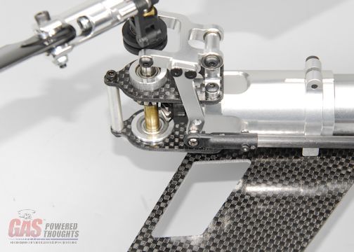 Install T/R rear control ball link this completes the assembly of the t/r Video Build Narrative Next Step Install canopy Last edited by carey shurley; 08-19-2021 at 08:00 PM.. |
|
|
|
|
09-14-2012, 05:19 AM
|
#14 (permalink) |
|
Registered Users
Thread Starter
Join Date: Apr 2004
|
In this step the canopy will be prepared and installed
in this build I'm using the optional Century "california" style Radikal 30 canopy. here you can see the parts needed to mount it  Canopy Parts - Century Optional California Canopy its necessary to create mount holes in the bottom of the canopy for the lower mount. So mark the canopy in these positions 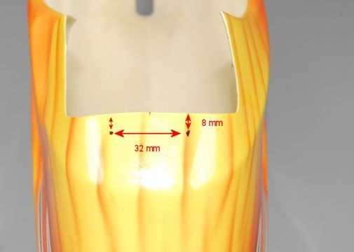 Lower canopy mount position then either ream or carefully drill 3mm holes for the mount screws 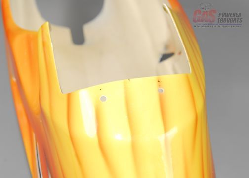 Lower canopy mount holes the mount screws for the lower canopy mount go here 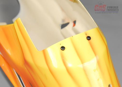 Lower canopy mount screws and they screw into the flat canopy mount as shown. The canopy mount has a square edge side and a beveled edge side. Mount it with the beveled edge side towards the back of the canopy. This will guide the canopy plate into the canopy mount 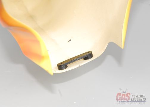 Lower canopy mount installed work the grommets into the two holes in the back of the canopy. you may have to slightly open them. Apply some CA from the inside but be careful not to let it run onto the canopy finish, it will damage the clearcoat 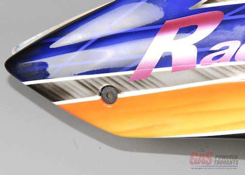 Rear grommets installed so the canopy mount installed into the bottom of the canopy will slip over this plate as the canopy is pushed over the chassis 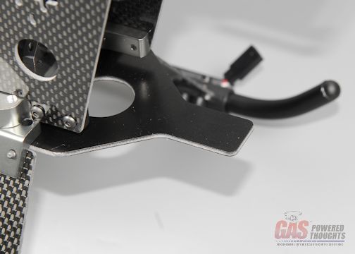 Front lower canopy mount plate and the two grommets on the back of the canopy will push over these canopy mount studs on the chassis 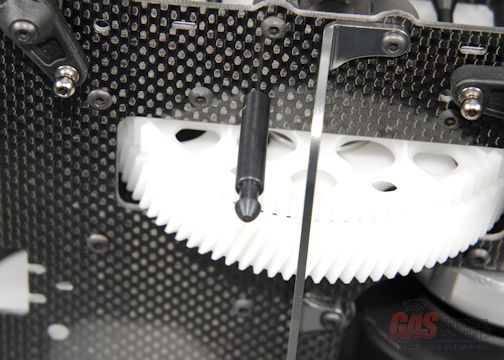 Rear canopy mounts here you can see the canopy installed and the rear canopy studs engaged 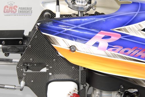 Rear canopy mounts engaged finally here's the optional California style Radikal 30 canopy installed on the model 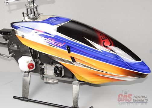 Optional California canopy installed Video Build Narrative Next Step complete motor configuration Last edited by carey shurley; 08-19-2021 at 08:00 PM.. |
|
|
|
|
09-14-2012, 05:20 AM
|
#15 (permalink) |
|
Registered Users
Thread Starter
Join Date: Apr 2004
|
The bulk of the model assembly is done at this point. We've left some of the components off of the motor that are necessary like the carburetor and muffler. Here you can see some of the required and optional parts
The muffler shown is an optional Century muffler that can be purchased separately or is included in some of the HWC engine packages 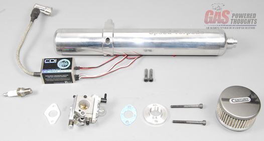 Parts to complete HWC engine The air filter assembly shown here is included with the HWC motors. There are many air filter assemblies available on the market, I HIGHLY recommend you use some sort of air filter here's how the carb stack goes together with gaskets/etc 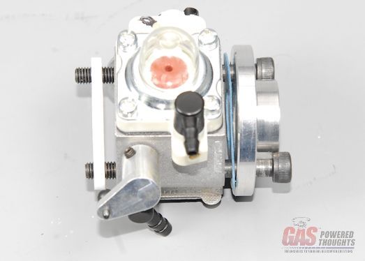 Carb parts stack the carb mounts to the engine isolator block as shown 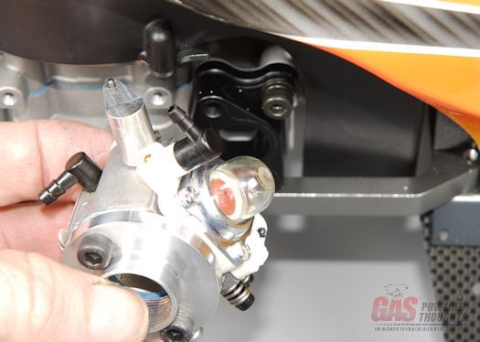 Carb mounting position use RTV or a VERY SMALL amount of HD thread lock (red) to attach the carb 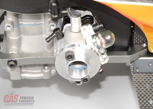 Carb Mounted The century air filter spins onto the carb mount plate. Use some RTV on the threads so this doesn't come off 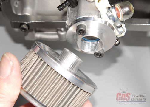 Air Filter Position Note, if you are using this and you when you install it the logo is upside down, then remove the mount plate on the outside of the carb and flip it over. It will then install as shown. 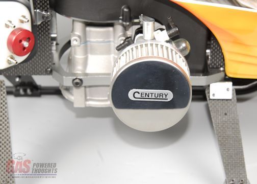 Air Filter installed You can use the stock zenoah muffler, or the optional century mufflers with no issue. If you want to run other optional mufflers you'll need to provide some sort of spacer so that they clear the motor/landing gear frame. If you use the Century muffler stack the parts as shown for install 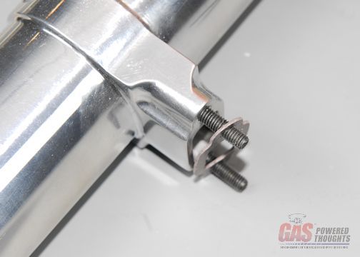 Muffler Parts stack and here you can see the muffler installed. Use some hi-temp RTV on the mount bolts 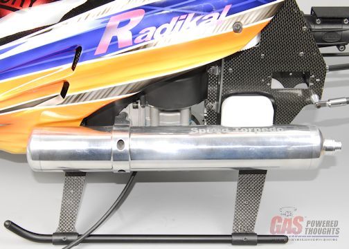 Muffler Installed install the spark plug, if it was not provided with the motor MAKE SURE you use a resistor plug or the interference generated WILL CRASH YOUR MODEL!! 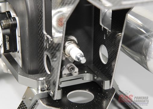 Spark Plug installed If you're using an HWC motor, it will include an EI system. The position shown is one of the possible positions it can be mounted. if you're using a std Zenoah PUH motor, the coil is already mounted on the motor and the plug wire goes through the small hole on the right frame side 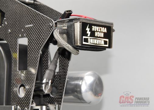 EI System Installed more to come Video Build Narrative Next Step Fuel Tank/Carburetor Plumbing Last edited by carey shurley; 08-19-2021 at 08:01 PM.. |
|
|
|
|
09-14-2012, 05:20 AM
|
#16 (permalink) |
|
Registered Users
Thread Starter
Join Date: Apr 2004
|
Fuel tank plumbing on a gas helicopter is a bit different than that on a typical glow model. To better explain it, I wrote an article about it that you can find HERE
lets review the fuel tank setup on the Radikal. Here you can see the tank put together, regardless of whether you built it using my optional approach or the std tank, the connectors are the same. The top two outlets are for vent/overflow/fuel return. The bottom connector is the fuel inlet. Fuel Tank outlets There are any number of ways this plumbing can be done. If you have a proven way, use it. Here is how I've plumbed it and I assure you it will work Here are the parts used, tygon fuel tubing, viton fuel tubing, a T fitting, a fuel end plug, some velcro and a plastic thread spool. Note: you MUST use gasoline proof tubing such as tygon, neoprene, viton, etc. Silicon tubing typical of glow models will melt 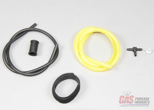 Fuel tank plumbing parts start by building the fuel inlet/return lines as shown. These lengths will work with either tank setup 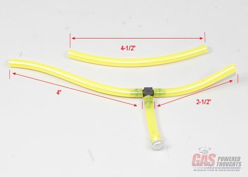 Tygon connectors connect the fuel inlet as shown. I recommend you do NOT include any sort of fitting in this line to avoid air bubbles 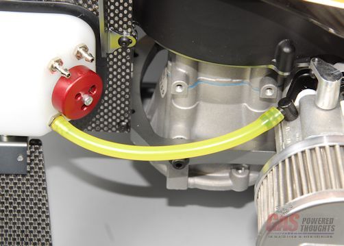 Fuel inlet install the fuel overflow as shown. This will return fuel to the tank when you prime the carb and will be used to fill the tank. The length of the tube with the plug is up to you. Insert a plug of some sort in the end. This is is a Thunder Tiger plug 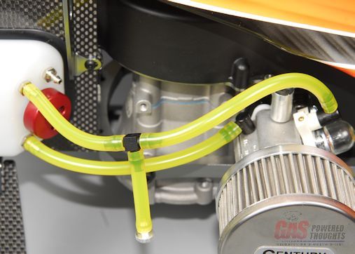 Fuel overflow to avoid having the tubing flopping around, use velcro to affix these two lines 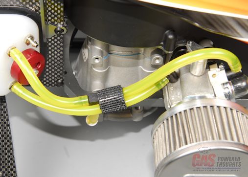 Affix fuel tubing now onto the fuel vent. If you read my tank thread, you know you can either use a one-way valve or a looped fuel tube. Because all of the fittings are exposed here I think its neater to use the loop method. Both should work because this fuel tank is very hard and stiff. so using the thread spool, wrap the fuel vent tubing around it and then secure it with velcro strips 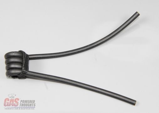 Fuel vent assembly here's another view of the vent assembly. I'm not going to provide lengths here because you can route this however you want  Fuel vent - side view so one end of the vent connects as shown on the fuel tank 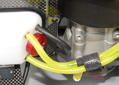 Fuel vent connected I've made the line long enough that the vent loop can be affixed to the bottom of the landing gear frame 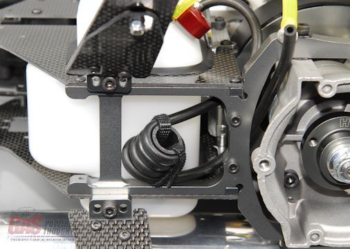 Fuel vent loop location and here you can see where I affixed it using velcro 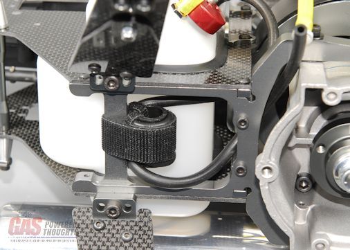 Fuel vent loop affixed thats it, the carburetor plumbing is complete. The tank is filled by removing the plug and pumping fuel in until you either stop or it overflows from the fuel vent line. The downside of this setup is the only way to remove unused fuel is to remove the fuel feed and pump the fuel out through the fuel pickup in the tank. Again I do not recommend putting any sort of connector in the fuel inlet  Fuel tank/carburetor connected Video Build Narrative Next Step install Control system Last edited by carey shurley; 08-19-2021 at 08:02 PM.. |
|
|
|
|
09-14-2012, 05:20 AM
|
#17 (permalink) |
|
Registered Users
Thread Starter
Join Date: Apr 2004
|
The last major set of components to install is the control system. There are two aspects to this:
Of course everybody has their favorite radio to use, but I'll show you the minimum you need to make it work you'll need 5 servos, one of which is designed for T/R use, if your model is FBL you need an FBL system and a battery if you are running the HWC EI motor or any motor that uses the RcExl ignition system, you can use a single battery to run everything. Use servos that are rated for whatever voltage your air battery provides OR use a regulator(s) as needed. remember that FBL systems work servos really hard and the vibrations from the motor are hard on the t/r servo so don't fool around with over driving the servos on their rated voltage. You'll also see a Stator Gator in here, this is a totally optional way to provide RPM sensing for your governor. If you have the HWC EI system, you can use the "tach" wire out of the EI system as long as you make sure to strip out the red/+ wire otherwise you'll hurt your electronics 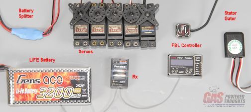 Electronics Used here are all the control system parts provided in the kit. Its really complete with everything to mount the servos included 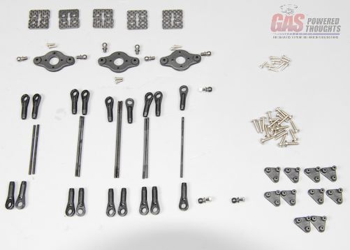 Control System parts The kit provides these parts to mount each servo. Two plastic servo nuts that permanently mount to the frame and graphite plates to retain each servo 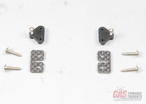 Servo Mounting parts here you can see how the servo nuts mount to the frame, the T/R mounts are the only ones that mount on the outside of the frames 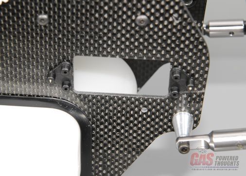 T/R servo mounts all the other servo mount nuts fit on the inside of the frames like the ones you can see here on the aileron servo. Note that one of the two mount holes to retain the servo nut is slotted, this allows you to slightly reposition to adapt to various servo sizes 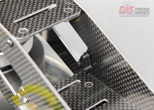 Servo Mount positions Once the servo mount nuts are in place, use the graphite plates and servo screws to retain all the servos. Here you can see the Pitch and throttle servos mounted and the orientation required for each 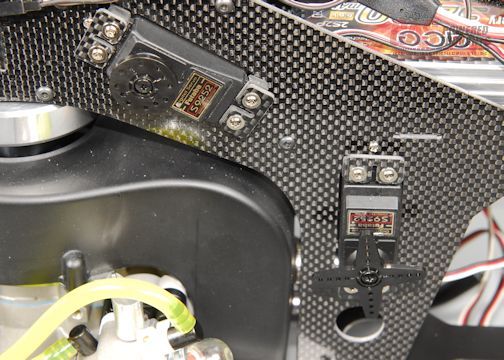 Pit/Throttle servos mounted and here you can see the elevator servo mounted at the rear of the frame. Note its orientation 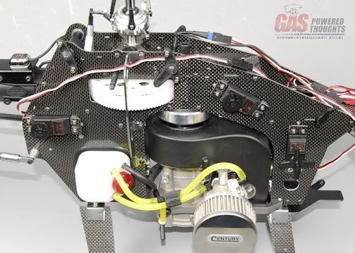 Elevator servo mounted and here are the aileron and t/r servos mounted on the left side of the frame 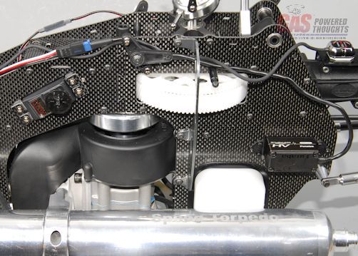 Aileron-T/R servos mounted there is no set way to install all the electronics. Its totally dependent on how you like to set this up. in my setup you can see where I've put the battery and FBL controller as well as the Rx. Make sure you route the wires so they don't rub on the graphite or wrap them in something to protect them 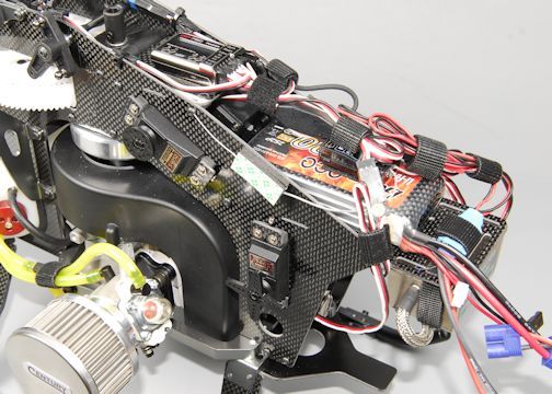 Electronics installed - right side view and heres a view of the mounted electronics from the left side of the model 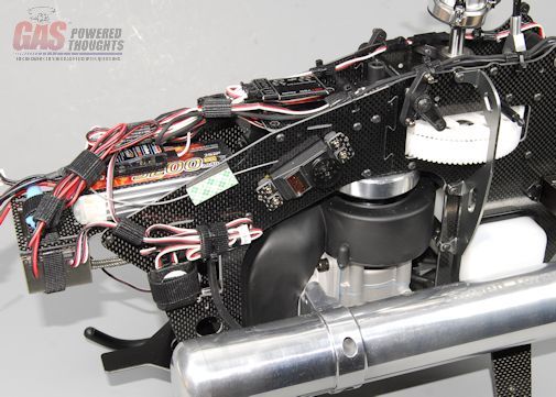 Electronics installed - left side view the kit includes some custom made servo arms for the swashplate servos. Here's how you are going to assemble them. you need to power up your control system and find the center point for all the servos before connecting any of the linkages. You'll be using small servo wheels that are appropriate for your servo If you want to use your own servo arms, you'll need something that has mount points 30mm apart or 15mm each from the center 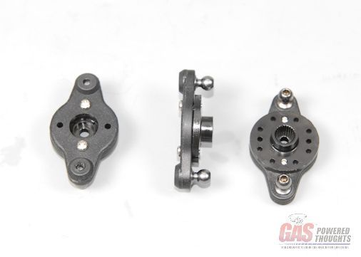 Ele/Ail/Pitch Servo Arms build the control rods as shown. If you don't use Futaba servos you may have to slightly adjust these these are really tight!!!! The good news is that the rods are all correct lengths and thread really securely into the ball links NOTE: the control rod lengths in the manual I have weren't all correct. What you see mounted on the model correctly with the servo orientations shown 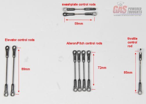 Build control rods before installing any other rods, snap on the aileron/pitch rods that connect the front bellcranks to the swashplate 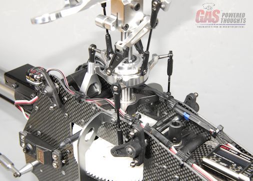 Install Ail/Pitch Swashplate control rods now you can build the servo arms for the swashplate. Use CA on the balls that thread into the plastic. The arms will bolt to your servo wheels using the small screws, use CA to make sure they don't come out 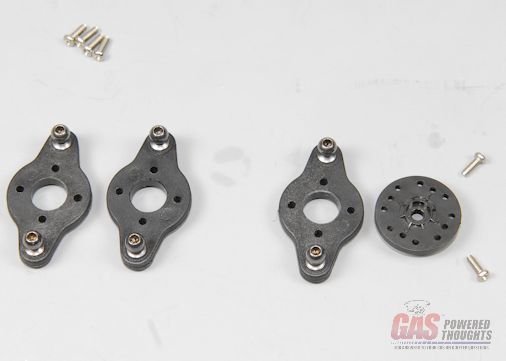 Ele/Ail/Pitch Servo Arms - mounting Put the servo arm on the pitch servo as shown, it will mount at a 90 degree angle to the servo 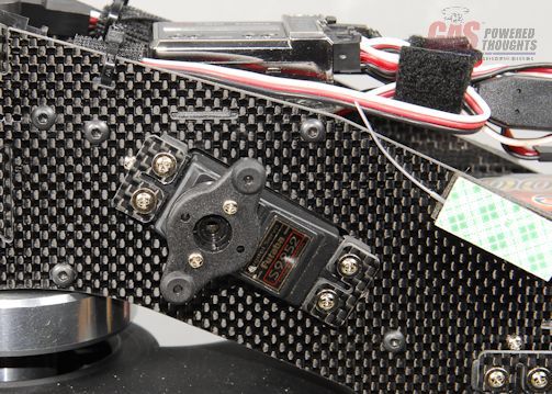 Install Pitch servo arm the same is true with the aileron servo on the left side of the model 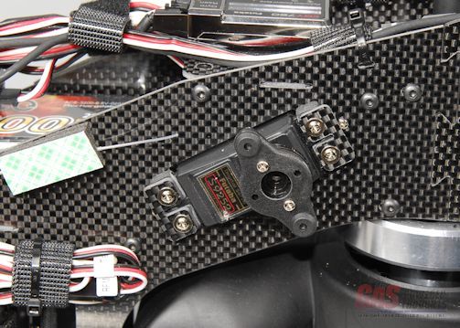 Install Aileron servo arm the elevator servo arm isn't as easy, you want it to mount parallel to the elevator bellcrank when the swashplate is at its mid position. If you have made up the rods at equal lengths this will be easy to determine 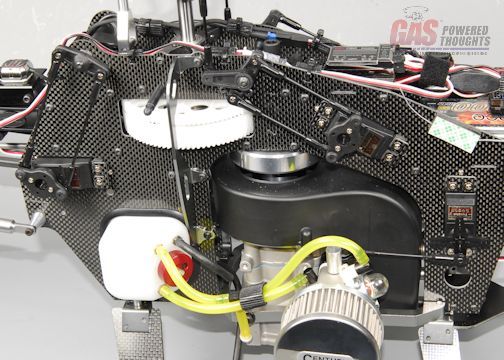 Install Ele/Pitch/throttle rods install the pushrods for the aileron and pitch servos as shown 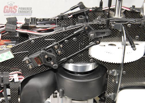 Install Aileron rods An unexpected problem surfaced when it came time to connect the t/r servo. mount the ball on the outermost hole on a servo arm (or whatever is appropriate for your gyro). But once the elevator servo is installed, you can't really get to the t/r servo. So I had to remove the elevator servo to do this and then replace it when I was done 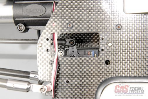 Connect T/R servo rod the target is for the t/r servo to be exactly centered and the t/r pitch mechanism to be centered on the tail. Depending on your servo it may or may not be. If its not, unclip the rear link from the t/r bellcrank and adjust the t/r pushrod length by threading/unthreading it 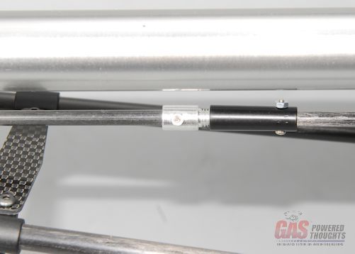 T/R control rod adjustment when its the right length, the t/r pitch change mechanism will be in this position. once this is set, apply plenty of thread lock to the pushrod threads or use thin CA on it 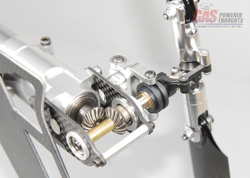 Center T/R pitch control to complete the t/r pushrod installation, position the two supports as shown 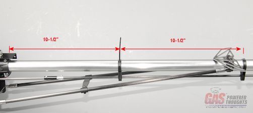 Position T/R supports the kit includes tie wraps to affix the supports. there is a small slot just up against the tail boom where it slips through. Tighten them up and make sure the rod can still move smoothly I'd suggest using thin CA to fix this supports to the boom and also very carefully applying it to the little blocks in the control rod supports. Over time these will loosen up and flop around if you don't secure them 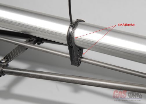 Affix T/R supports Video Build Narrative Next Step Main rotor blades Last edited by carey shurley; 08-19-2021 at 08:03 PM.. |
|
|
|
|
09-14-2012, 05:20 AM
|
#18 (permalink) |
|
Registered Users
Thread Starter
Join Date: Apr 2004
|
The final step to complete the model assembly is to install the main blades
you can use whatever blades you want, I wouldn't go shorter than 690mm nor longer than 700 I'm using a set of Rotor Tech blades as shown The blade grips are setup for 16mm roots and 5mm bolts. If your blade roots are thinner than that you'll need to use spacers. They usually come with what is needed 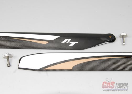 Rotor Tech Main Blades They bolt on normally, you want these pretty tight especially with FBL systems Note: the kit doesn't include a head button but the head is setup to accept one. I found that the Align Trex head buttons bolt right on if you want one 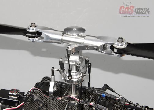 Main blades installed Video Build Narrative Next Steps Build Completed Last edited by carey shurley; 08-19-2021 at 08:04 PM.. |
|
|
|
|
09-14-2012, 05:20 AM
|
#19 (permalink) |
|
Registered Users
Thread Starter
Join Date: Apr 2004
|
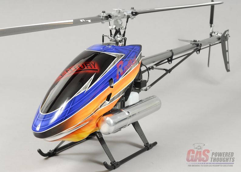
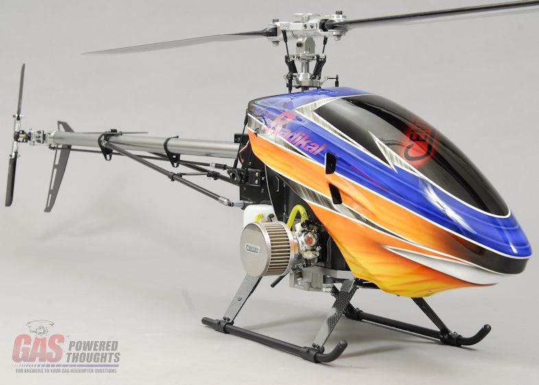
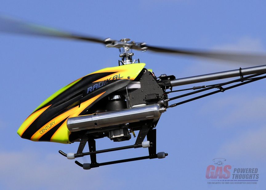
Here are some views of the completed model
please note, there are a number of optional components included on this model. Some of the optional parts shown that are not included in the kit are:
  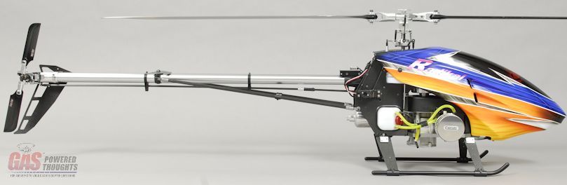 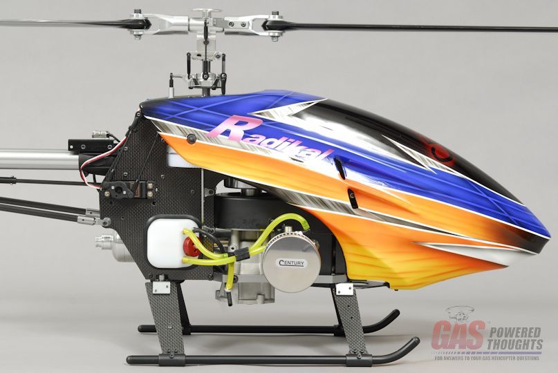 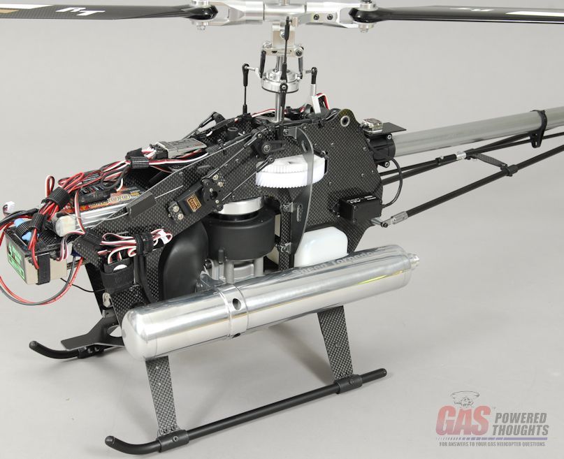 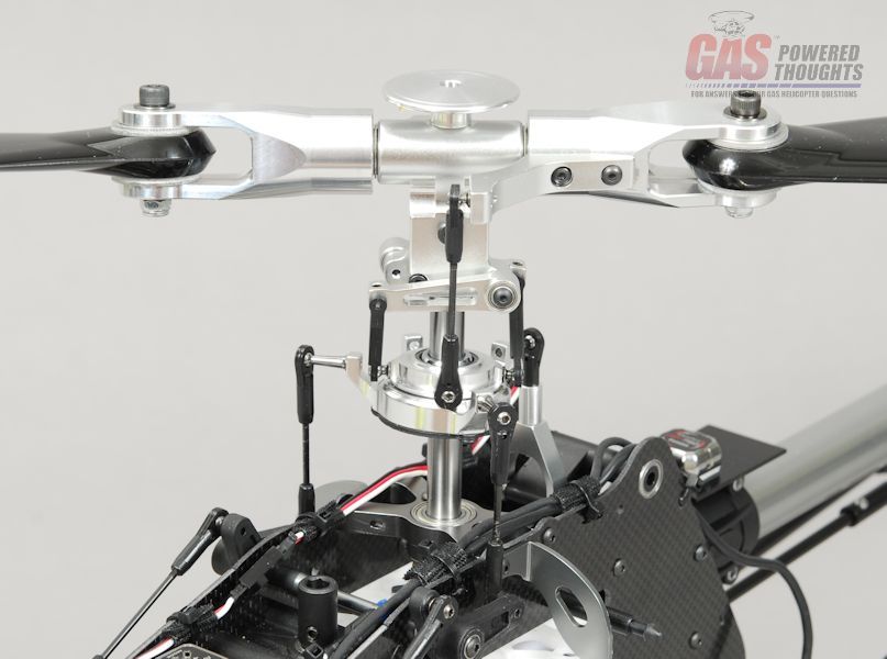 Last edited by carey shurley; 08-19-2021 at 08:04 PM.. |
|
|
|
|
|
|
«
Previous Thread
|
Next Thread
»
| Thread Tools | |
| Display Modes | |


 Linear Mode

|
|


